
Motorcycle Camping Trailer Build
Trailer Articles
>
Building a Motorcycle Trailer and Camp Outfit
|
INSTEAD of the ordinary sidecar so much used by motorcycle owners I constructed the pull behind motorcycle camping trailer and camp outfit herein described to take its place.
A companion and I made a 600-mile tour with it over some of the worst desert and mountain roads in the western states. The trailer proved its
practicability and its advantages over the sidecar. There was no side drag on the motor, and, as the pull was straight backward, the motor was
held steady in the sand ruts. Another great advantage over the sidecar is that the pull behind trailer can be detached by pulling out a pin when it is
desired to make short side trips. Many conveniences may also be incorporated in it that would be impossible with a sidecar permanently attached
to a motorcycle.
The complete equipment consists of the following units: trailer car, nested mess kit, tent and sleeping bags, and a complete
photographic developing outfit for field work. The total weight of the outfit, with the necessary food-stuffs and motor-repair parts, is
slightly under 250 lb. This weight may seem excessive, but it did not prove so, even on had roads, and upon one occasion 100 miles of good
road was covered in five hours.
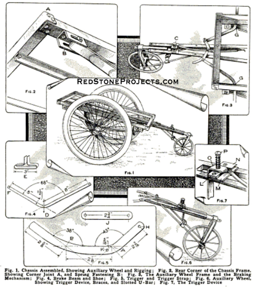
The first part of the equipment to be taken up in detail is the motorcycle trailer chassis, which is shown in Fig.
1 ready for the installation of the body. The illustration shows the axle straight. A 3 or 4-in. dip made in it will lower the center of
gravity. The bend in the axle being outside the springs, the tread will be about 6 in. wider, but otherwise the dimensions given are
satisfactory.
The measurements for the chassis are as follows: The axle is of steel, 33 in. long and 7/8 in. in diameter, turned down
at the ends to fit the cones of the ordinary sidecar wheels, and threaded on each end to receive a ½ in. castellated nut, which is locked
with a cotter. The springs were obtained from the junk pile of a local wagon maker. They consist of the lower halves of ordinary buggy springs,
measuring 33 in. long and 1 1/4 in. wide. As the springs were too stiff, only the three larger leaves were used, these being secured to the
axle with strap bolts or axle clips.
One of the rear-corner joints is shown in Fig. 2. The sidepieces arc 38 1/2 in., and the ends 19 in.
long, and of 1 1/2 by 1 1/2-in. angle iron. One face of the end pieces is cut 22 in. long, to permit a 1 1/2-in. lap for riveting to the
side members, as shown at A. The method of mounting the springs is shown at B. A piece of 1/8-in. sheet steel, 3 by 4 1/2 in., forms the
rear bracket, which should be of such quality that it will stand hardening. A slot,1 ½ in. long by 5/16 in. wide, is cut through the
sides to receive a hardened. steel bolt passing through the spring end in such a manner that it will ride in the slots of the bracket.
The front spring bracket is similar but without a slot, having a hole for the bolts. and does not need to be hardened.
The tongue, draw head, and automatic brake are shown in Fig. 3. The tongue consists of two pieces of 1 by 1/8 in. angle iron 52 in. long and
the draw head is made of a 6 in. length of 3/4in. pipe, with a pipe cap. The lengths of angle iron are bent slightly, at C, to permit
bolting them parallel with the draw head, and to make a spread of about 10 in. where they connect with the front member of the frame.
The draw head is attached to the tongue pieces with machine screws locked with lock washers. The ends of the screws that project inside
of the pipe should be dressed off smoothly to permit the free action of the drawbar.
The drawbar is made of a machine-steel eyebolt,
6 in. long and 1/2 in. in diameter. The bolt slides through a hole in the cap, against which a spring is placed. It exerts pressure
on two nuts on the end of the drawbar, working easily inside of the draw head. The spring can be adjusted by the nuts on the bar.
This arrangement forms a swivel-and-spring draw head, which is very important, as the safety of the trailer depends greatly upon it.
The nuts on the end of the drawbar should he securely locked, to prevent them from coming off and thus releasing the drawbar.
A little cup grease should he packed in the spring for lubrication, as the drawbar is constantly working back and forth when on the
road.
The automatic brake may appear unnecessary, but it is a great convenience when some of the draft rigging breaks. Also, in an
emergency the trailer may be cut off while in motion to prevent a "spill," and the brake will prevent it from running over a bank
or into another vehicle. When making camp, it saves marching for something with which to chock the wheels. If the car is taken down
a steep place by hand the brake is needed. It is self-locking and equalizing when set. It took considerable experimenting to find
the exact shape and dimensions of the levers.
The working details are shown in Fig. 4. Two brake beams and shoes are required,
which are made from metal, 1/2 in. wide and 1/4 in. thick. The beams are bent as shown at D, which is the center of the angle and
the point where the tangents of the two legs cross each other, the exact locations of the holes being found from this point. The
shoes E are made of steel, 1 in. wide and 1/16. in. thick, riveted to the beams at F. The two beams are pivoted to the frame at G,
Fig. 3. 4 1/2 in. from the front-end piece, and 1/2 in. from the edge of the side member, inside measurements, the pivot bolts
being 3/16 -in. stove bolts with lock washers.
The bends, to make the peculiar shape of what may be called the trigger. must be
made accurately, to ensure the proper adjustment and operation of the mechanism, hence the working details must be observed.
The lever is attached, at H, Fig. 5, to the right brake beam, the short piece J being coupled to the trigger at K. and to the
left beam; stove bolts with locknuts being used throughout.
The automatic release, Fig. 6, consists of an 8 in. auxiliary wheel
supported in a U-shaped bracket made of channel iron. 6 in. long on each leg. A 1 in. slot, wide enough to permit the shaft of
the small wheel to slide freely in it, is cut in each leg. The bracket is fastened to the cap on the draw head with a machine
screw. The sides of the channel are filed at an angle to fit the cap snugly when the bracket, drawbar, and braces are joined.
They should be joined so that the longer sides of the triangle formed are equal.
The braces are made of iron rod having eyes formed in their lower ends to fit the wheel shaft. They are flattened on the opposite ends for
bolting to the tongue sections, their length being such that the center of the shaft will be about 13 in. from the point at which they bolt to the tongue.
|
|
|
If the parts are set properly the auxiliary wheel will work freely in the slots, the natural spring in the brace rods tending to
hold the wheel at the bottom. The release-catch feature is simple. At a point 8 1/2 in. from the front member of the frame, two holes
are drilled and tapped for machine screws.
Two plates, L and M, Fig. 7, one 2 3/4 in. long. 1 1/2 in. wide, and 1/16 in. thick, and the other
2 3/4 in. long, 3/4 in. wide, and 1/4 in. thick, are attached to the tongue by the screws as shown. A small piece of metal N, is placed on top
of the thicker plate, to prevent the trigger from rising out of place when the catch O is pushed up. A carriage bolt, P, is screwed into
the plates at their center, with a locknut to hold it on the underside. The catch O is drilled to permit free action on this bolt. A light
spring is placed between the catch 0 and the head of the bolt. The release is fastened to the braces by means of a strap and stove bolts, as
shown in Fig. 6.
The action of the automatic trailer brake is as follows: When the trailer is released from the motor the tongue drops; the auxiliary wheel,
coming in contact with the road, rises in its slots, pushing the catch up to clear the trigger, and a coiled spring at the middle draws the
brake beams into action. This spring does not hold the brakes in contact with the wheels, but merely starts the action. The braking power is
derived from the back pressure on the rod braces. which is communicated to the lever arrangement on the brake beams. The greater the weight
pressing down on the auxiliary wheel the greater the braking power.
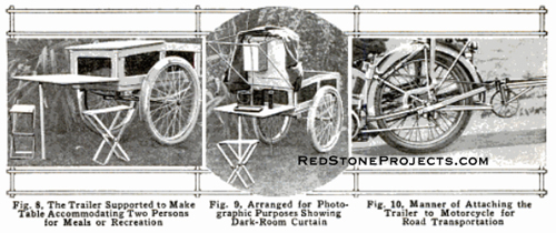
The design of the motorcyle trailer body and the arrangement of the covers to form tables
are shown in Fig. 8. The dimensions of the box are such that it will fit snugly in the chassis frame. It is made of 1/2 in. lumber with corner
and edge strips to reinforce the joints. The inside edges of the strips are beveled to give a neat appearance to the panels. The box is
water-tight, 13 in. deep at the center and 11 1/2 in. at the ends, the floor resting on the side members of the frame and on the tongue at
the center.
A tank, 17 in. long, 10 in. wide, and 4 in. high, of 3-gal. capacity, for a gasoline supply, is set in the rear of the body.
It is held in place with cleats, and is made of galvanized iron, with reinforcing plates on the ends.
The front cover is so arranged that it can be attached to the rear of the body for use as a mess table, and for photographic purposes.
Folding standards, at the end of the tongue, at the rear of the chassis and under the table, together with the brake make the whole stand firmly.
When the table is used for photographic purposes the rear cover, which is hinged to the body, is braced in a vertical position, as in Fig. 9.
A collapsible wire frame is attached to the cover by means of screw eyes, on the underside, and a light-proof bag, large enough to enclose the
table and the operator, forms a dark room. As it is used only at night, it is satisfactory for this kind of work.
As the motorcycle was electrically equipped for lighting, a small lamp, not shown in the illustration, was bracketed to the rear of the body.
The feed wires were conducted to the end of the tongue, where slip connections were provided to connect with a terminal on the motor draft rigging.
A long extension cord was provided, permitting the motor to be set at a distance from the car when in camp. The lamp proved to be convenient, being used
as a tail light for night traveling, as a dark-room light, and as a table lamp, when the red lens was removed.
The method of coupling the trailer to the motorcycle is shown in Fig. 10. As slightly differing methods will be necessary with varying types of
motorcycles, it is offered as a suggestion only. The motorcycle which was used to tow the trailer was provided with sidecar lugs immediately forward
of the rear axle, and with small luggage carrier lugs on the rear forks. A U-shaped piece of strap iron, 1 1/4 in. long and 1/4 in. thick,
was bolted to the sidecar lugs at such an angle that the draw head of 5/16 in. by 1-in. steel, bolted at the center, would hold the
trailer horizontal. The upward thrust of the trailer was prevented by the U-piece resting against the nuts on the rear axle of the motor,
the downward thrust being held with 1/4-in. stay rods running from the lugs, on the rear forks, to the outer curve of the U-piece.
A large cotter, slightly spread, forms the coupling pin and a cord is attached to it so that the man on the rear seat may release the
trailer in the event of a skid or fall. All nuts and bolts must be locked either with split washers or cotters. The load should be
packed with the heaviest articles in the center in order to balance the car. Several screw eyes should be placed in the sides of the
body near the floor, an a lash rope run through them, with which to lash the load solidly in the car. This prevents shifting and protects
the contents in the event of a "tip-over."
|
|
|
The Mess Outfit
The mess outfit is well adapted for motorcyle camping, as it provides nearly everything necessary for two persons, and is contained in a small package.
While it is designed particularly for motorcycle use, it should prove a serviceable addition to the equipment of the automobile tourist
and could easily be made to serve for four or more persons, without enlarging the space occupied by it. Space for extra cups and plates
may be obtained by utilizing the space used for food, in the kit for two persons. An elaborate set of tinners' tools is not necessary in
making the outfit vise, snips, mallet, pliers, hammer, and a soldering iron being the articles required. Short lengths of angle iron, of
different sizes, clamped in a vise form the mandrel upon which the bends are made.
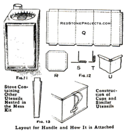
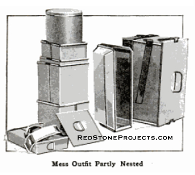
The complete outfit nested inside the combination stove
ready for transportation is shown in Fig. 11. It occupies a space 7 1/4 by 7 1/4 by 12 in., and weighs slightly less than 11 lb. without
foodstuffs. It contains the following utensils: coffee pot, two cups, one bowl, stewpan, frying pan, two plates, sugar can, two sets of
knives and forks, an extra spoon, and a 2-gal. bucket. There is room also for 3 lb. of bacon, 1/2 lb. of butter, cans of pepper and salt,
1/4 lb. of tea, and a small dishcloth.
Three sheets of heavy tinplated sheet metal, a piece of light galvanized iron, 12 by 36 in., and
a piece of black sheet iron. 15 by 50 in., of medium thickness, will provide all the necessary pieces with the exception of the gasoline
tank for the stove. If it is desired to use the type of stove shown, a small amount of galvanized iron, of medium thickness, will also be
required.
The patterns for cutting and forming the different utensils are shown in Fig. 12. The main pattern Q is for one of the sides.
The sheet metal is folded on the dotted lines and the joint placed in the center of one side. On each edge 1/8 in. and 1/4 in. are provided
to form the clinch seam, and 1/8 in. on the bottom edge for the joint. At the top 3/16 in. is provided to form a roll around the reinforcing ring.
|
|
|
The bottom pattern is shown at R, the dimensions of which is best determined after the sides have been formed. It is 1/8 in. larger than the bottom half of the clinch.
|
|
|
The first operation of attaching the bottom plate is shown at S. The lap of the bottom is folded over the side lap, and clinched as shown at T.
The top roll around the ring, which consists of ordinary galvanized telephone wire, is formed as shown at U. The side seams are clinched in the
same manner. A small piece of steel, similar to a rivet set, with a notch the size of the seams cut in its face, aids in making the clinch
properly.
The detachable handle of the cups and the coffeepot are constructed and attached as shown in Fig. 13. The tongue at the top is
formed into a hook and hooked under the wire ring, a bit of the metal of the side having been cut out to permit its insertion. A small strap
soldered to the side of the utensil permits the handle to slip down under it when squeezed slightly. The handles are reinforced along the edges
with a small wire and a roll.
All the utensils are made in the same manner, with the exception of the stewpan, which has the ends clinched in,
the sides and the bottom being made of one piece. The handles of the stewpan are not detachable, but form clasps to hold the lid tight, when
the equipment for it and other contents are nested inside. The construction of the bucket is similar, except that larger seams are made.
Since a clinch seam is not water-tight, all joints in the bucket must be soldered.
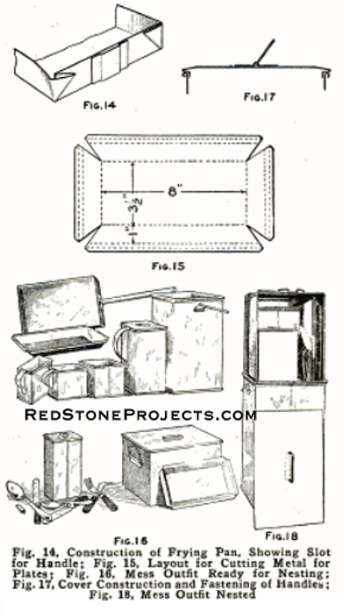
The frying pan is made of the black sheet iron. It is constructed without seams, as shown in Fig. 14, the corners being folded and riveted.
A strap is riveted on one end, to receive the detachable handle, which is a short piece of 1/8 by 3/4-in. strap iron, with a hook bent upward on the end.
The construction of the plates is shown in Fig. 15. They have a 1/2-in. double, flat brim around the edge.
Beginning with the smallest utensil. shown
in the rear row in Fig. 16, the inside measurements are as follows: first cup, 3 1/2 in. square by 4 in.; second cup, 3 3/4 in. square; coffee pot,
4 in. square by 8 in.; bowl, 4 1/4 in. square; sugar can, 1 by 3 1/2 by 6 in.; plate, including rim, 7/8 by 5 1/2 by 9 3/4 in.; stew pan, 5 1/2 by 6 by 9 3/4 in.;
frying pan, 11 1/2 by 6 1/4 by 10 in.; bucket, 6 1/2 in. square by 11 in. The covers of the coffee pot and the stew pan are made to fit. The method of forming
the edges of the covers and of attaching the handles is shown in Fig. 17.
The assembling of the mess kit is shown in Figs. 16 and 18. When the articles are
nested inside the coffee pot, enough room is left on top for the half pound of butter and the bacon. The lid of the stewpan is shown removed
in Fig. 18, and space can be seen at the top for cans to hold salt, pepper, tea, and similar supplies.
The stove was designed so that wood or
gasoline could he used for fuel. Double the space is needed when gasoline is used, in order to provide a storage tank for the gasoline.
The stove is constructed of heavy sheet iron. The measurements inside are 7 1/4 in. square by 12 in. A 3-in. hole is cut in one end, and a
6-in. hole in the other. An old brazing torch was used to make the burner for the gasoline stove.
The gasoline supply was set in a galvanized-iron
tank, 4 in. by 7 in. square, in much the same manner as it was in the origina torch. The generating pan was removed from the feed stem and
placed on the valve stem, permitting generation of gas in the usual way. The pump was placed in a corner. In order to spread the flame
over a larger area, a burner cap. taken from a gasoline stove, was attached to the top of the fire head. A stay bolt was run through the
center of the tank to reinforce it to withstand the air pressure. Care must be taken not to have too great a pressure in the tank.
When the stove is used with wood as a fuel, it is placed in a horizontal position, with the open side over a small depression in the ground.
A heavy wire screen is hooked over the inside edges, where they are turned in, forming a grate. This gives a draft for the fire.
The Photographic Outfit
The photographic equipment need not be detailed completely, as the only point of special interest is the method of washing and drying plates.
After taking them from the hypo tank, they were placed in the wash tank. The bucket hanging at the rear lid of the body of the car was filled
with water, and a rubber siphon drew the water down to the wash tank, from which it ran to the ground. After the plates had been washed, they
were placed in an alcohol tank. The alcohol displaced the water in the emulsion, causing the plates to dry in a few moments, when placed
before an electric fan driven by current from the motorcycle storage battery.
The Tent and Sleeping Bag
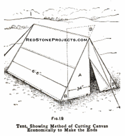
For the making of the small tent. and two sleeping bags, 21 yd. of canvas are necessary, 8-oz. double-twist khaki drill being the most
suitable. One or more blankets for each bag are needed, depending on the temperature in which the bags are to be used. The dimensions of
the tent are approximately 6 1/2 ft. long, 5 ft. high, and 5 ft. wide. This is sufficient to cover a motorcycle and two persons. Two bamboo
poles support the tent at the front and rear, a rope ridge support being used.
The method of cutting and joining the canvas, which is 36 in. wide, is shown in Fig. 19.
|
|
|
Thirteen yards are necessary for the tent.
From this four lengths, 6 ft. 7 1/2 in. long, are cut, thus allowing 3/4 in. on each end for the corner seams, stitched together with laps,
as shown. One seam is at the ridge and the other in the center of the sides. A 1/2 in. hem is placed along the bottom edges.
The remainder is now divided and each section equally divided to form the four large gores, A, as shown in Fig. 19. Two of the gores are stitched
together their full length, forming the back of the tent, and the other two are stitched about one foot down from the ridge, leaving
an opening for an entrance. The front and back are next stitched to the side walls along their slanting edges. They will be a few
inches too long. The part left over is cut off, and the small gores B are made from these scraps. A hem similar to the one upon the
sides is next placed on the bottom edge of the end.
|
|
|
Eyelets with 3/8-in. holes are fitted along the bottom edges to receive the
large spikes used for tent pegs. The ridge rope is then run through the apex of the ends and fastened.
The sleeping bags are
each made of 4 yd. of canvas, fashioned like a long envelope. The upper side is 5 1/2 ft. long and the bottom 6 ½ ft., accommodating
a person of medium height. The blankets used inside of the bags should be stitched together with the seam uppermost and in the
middle. The top of the blankets should be left unstitched for about 18 in., as the bag may thus be more readily entered, and
the blankets brought closely around the neck of the user. A cord should be run through the bottom seam of the inner bag and
through eyelets in the corners of the outer bag, so that the bag may be anchored to a peg, making it easier for one to get
out of it.
In connection with the sleeping equipment, a poncho is desirable and can be made from a 48 by 72-in. piece of
black oilcloth. A hem should be run around the edges of the oilcloth, and five garment snaps should he sewed on one long edge,
in order that the poncho may be thrown around the shoulders and fastened in front.
A poncho of this type protects the upper part
of the body when walking or riding in the rain, and may be spread over the sleeping bags to protect them when used in the open.
Two ponchos may be snapped together to form an auxiliary roof for the tent. A poncho is the handiest article in camp on a wet day,
with the possible exception of a water-tight match safe, and, of course, every camper should have one of these.
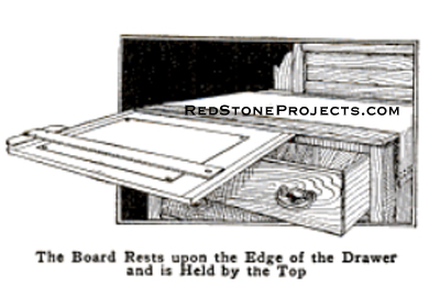
Dresser as a Drafting Table
A dresser, or bureau, may be made to do service as a drawing table and will be found convenient by students and others who make
drawings occasionally. The sketch shows how the board is rested on the edge of the open drawer, and held under the dresser top.
For use in a standing position the dresser will be found convenient, whereas a bureau gives better service for the seated position.
|
|
|
The board should be placed at the left-hand edge of the dresser, so that the same edge of the board extends about 1 in. beyond the
side. If the drawer is not firm, small wedges may be inserted between it and the slides on which it rests.
- Contributed by Raymond B. Rogers, Newberg, Ore.
|
Trailer Articles
> Building a Motorcycle Trailer and Camp Outfit
|
| |