|
|
Catapult - Build
a Catapult - Catapult Design Plans
From The Crossbow
by Sir Ralph Payne-Gallwey 1903
| Catapult Dimensions and Assembly |
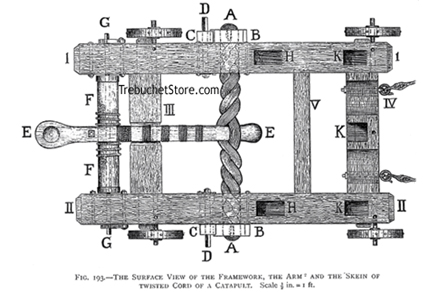
Figure 193. Catapult
- Plan View of the Framework, Arm,
and Skein of Twisted Cord of a Catapult.
|
I and II. The side pieces. These are each 10 ft. 6 in.
long and 1 ft. thick. They are 21 in. high at their forward ends in front
of the skein and are reduced to a height of 15 in. at their after ends
behind the skein; see figure 194 for a side view of the catapult.
III. The after cross-piece. This is 15 in. high and 1 ft. thick.
IV. The forward cross-piece. This is 21 in. high and 1 ft. thick.
The cross-pieces (III, IV) are cut into tenons at their
extremities and mortised into the side pieces I, II.
V. The small cross-piece (6 in. square). This gives additional
support to the sides of the catapult to enable it to resist the immense
force of the skein of twisted cord.
The inside width between the sides of the catapult (I, II),
when the cross-pieces (III, IV, V) are fixed, is 4
ft.
A, A. The skein of twisted cord. The ends of the skein
turn over the crossbars of the large wheels (B, B), which
twist the skein. See figures. 197 and 199.
C, C. The pinion wheels which turn the large wheels, B,
B.
By turning with long spanners the spindle heads (D, D),
of the pinion wheels (C, C), the large wheels (B,
B),
revolve and twist the skein of cord (A, A), between the halves
of which the catapult arm (E, E), is placed..
The skein of cord (A, A), is 8 in. in diameter.
F, F. The roller (7 in. in diameter), which winds down
the arm, E, E.
The two small cogged wheels, with their checks, which are fitted on
the ends of the spindle (G, G), prevent the roller from reversing
whilst the catapult arm is being wound down, figure 194.
H, H. The mortises cut in the sides of the catapult to
receive the tenons of the two uprights. Between the tops of these uprights
is fixed the cross bar against which the arm of the catapult rests, or
when released from its catch strikes. The uprights and the cross bar are
shown in figures. 194, 195, 196.
It will be noticed that the mortises for the tenons of the catapult
uprights, are placed well away from the circular openings in the sides
of the catapult through which the skein of cord passes. If these mortises
were cut too near the openings for the skein, the side pieces of the catapult
would be weakened.
K, K, K. The mortises for the lower tenons of the
three sloping supports which prevent the two uprights, and their crossbar,
from giving way under the blow of the released arm of the catapult, figures
195 and 202.
The upper ends of the two side supports are mortised into the tops of
the uprights, to which they are also bolted, figure 194 and 202.
The top of the middle support is mortised into the center of the cross-bar
that connects the uprights, figure 195 and figure 202.
Catapult Experiments and Testing
|
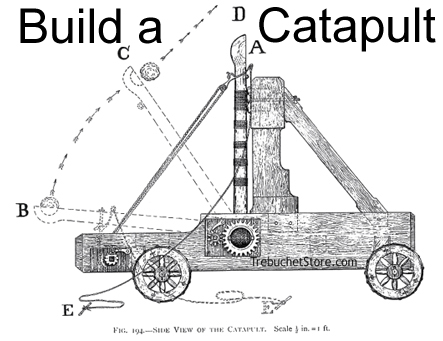
Figure 194. Catapult
- Side View of the
Catapult Built From These Plans
|
The catapult arm (A) is here, ready to be wound down by the
rope, 1 1/4 in. in diameter, that is attached to it and also to the roller.
The ends of the rope are passed through holes in the winding roller and
are then secured by knots, F, F, figure 193.
The upper part or bend of the rope is hitched by a slip hook to a ring
bolt which passes through the arm of the catapult. Figure. 200 describes
the ringbolt and the slip hook.
B. The position of the catapult arm when it is fully wound down
by the roller. The stone may be seen in the cup of the arm.
By pulling the cord (E), the catapult arm is released from the
slip hook and , taking an upward sweep of 90 degrees (see curved line of
arrows), returns to its original position, as at A.
C. The position of the arm of the catapult at the moment when
the stone leaves it. The stone is projected upwards at an angle of about
45 degrees, as represented by the straight line of small arrows that indicates
its flight after it leaves the arm at C.
When the arm reaches the point in its upward sweep at which its speed
is greatest, the stone instantly flies away in front of it. That is to
say, when the catapult arm decreases in speed, however slightly, it cannot
keep pace with the stone it projected the moment it reached its maximum
velocity.
This principle should apply equally to the bow and its arrow. In this
case I believe the arrow leaves the bowstring before the latter has returned
to its position of rest, or as it was before it was pulled back by the
archer to discharge the arrow.
When I originally directed my attention to building a catapult I concluded
that the medieval catapult plans and drawings, which depicted the arm of
the catapult in a perpendicular position, as in A, figure 194, were
incorrect.
My surmise was that a catapult design with a perpendicular arm would
merely bowl its stone along the ground, on the principle that the stone
was retained in the cup of the catapult arm till the latter was checked
by the cross-bar.
Carrying out this idea, I placed the winches of the first catapult I
made in front of the uprights and not behind them as in the weapon here
described. By this catapult design the arm when released had of course
an upward inclination when checked by its cross-bar. Such a position for
example as half-way between C and A, figure 194.
The result of this intended improvement on the ancient catapult design
was:
With a Sloped Arm
1. The cross-bar which checked the arm of the catapult was soon knocked
loose through being struck in an upward direction.
2. The range of the projectile was unsatisfactory through the catapult
arm being wound down only a short distance from its state of rest.
3. The projectile - as in the case of a perpendicular arm - left its
cup a considerable time before the catapult arm encountered the cross-bar.
On the other hand I found that:
With a Perpendicular Arm (A, Figure. 194)
1. The cross-bar was struck a level blow, or one that was taken by the
three supports which lean against its center and ends.
2. The range of the projectile was much increased owing to the additional
distance the catapult arm was wound down, and which caused the skein of
cord to be far more tightly twisted than it was when the arm rested against
the cross-bar in a sloping position before it was pulled back.
3. The projectile left the cup of the catapult arm as shown at C,
figure 194, and as it did with a sloped arm.
Detailed Catapult Plans Design
Figure 95 shows the large front cross-piece (IV, figure 193),
between the sides of the catapult, as well as the three supports that hold
the uprights and the cross-bar from movement when the latter is violently
struck by the released arm.
Click Here
to See a Catapult Animation.
|

|
Figure 195. Catapult
- Front View
Showing the Large Top Cross Piece.
Figure 196 shows the catapult arm, the rope which pulls down the arm,
the slip hook for releasing the arm when it is wound down, the winding
roller, the upper edge of the skein of cord, the winches, and the other
parts of the catapult previously described.
We also see in figure 196 the padded cushion against which the catapult
arm strikes with terrific force when its upper end is checked by the cross-bar.
The cushion is of the same depth as the cross bar. It is 16 in. long and
about 6 in. thick. It is made of soft hide, doubled and packed with horsehair,
and should be nailed to the catapult cross-bar.
Without this protection the catapult arm and cross bar would soon be
shattered.
|
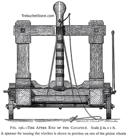
Figure 196. Catapult
- Rear View Showing the Rope, Winding Roller,
Slip Hook Trigger, Skein, Winches and Winch Spanner.
|
The catapult arm (of ash, straight grained and without a knot or shake)
is 7 ft. long and 4 1/2 in. thick, with rounded edges. It tapers from a
width of 8 in. at its butt end, to a width of 6 1/2 in. at the part above
the kingbolt where it commences to enlarge into the cup that holds the
stone.
The tendency of the arm of a catapult is always to draw out of the skein
of cord, in which its butt end is placed. This is the result of the strain
applied to the arm when it is being wound down by the roller. To prevent
this slipping of the arm its butt end should be slightly increased in bulk,
as shown in figure 193.
The cup or circular hollow at the end of the catapult arm - in which
the stone is laid is 5 in. wide and 2 in. deep at its center.
The arm should be tightly bound at short intervals with lashings of
quarter inch cord, figure 196. Sometimes an arm will endure the great strain
applied to it from the first and show no sign of fracture, though it may
bend not a little when, it is wound down to its full extent.
It is, however, probable that the first arm or two tried in the catapult
will give way, especially if too much initial pressure is put upon them.
The arm should be tested by degrees and only pulled down its full distance
after several trials at shorter ones.
The ancients had the same difficulty in obtaining arms for their large
catapults that I have experienced with smaller ones. For this reason their
engineers constructed the arm of a catapult of three longitudinal pieces.
They first fastened three smooth and closely fitting planks together with
glue and with small rivets; then they shaped the planks, thus held together,
into an arm of correct size and outline.
The catapult arm, except its enlarged head end, was next wrapped tightly
round its entire length with several layers, one above the other, of strong
linen soaked in glue, the linen being cut in strips about 3 in. wide.
Finally strong cord, also soaked in glue, was closely lashed over the
linen from the butt end of the catapult arm to the cup for the stone.
The arm was made on the same principle as a carriage spring, or a longbow
of several pieces, and was infinitely stronger and more elastic than one
formed of solid wood.
The Catapult Winches
|
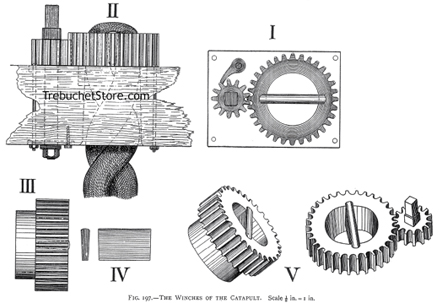
Figure 197. Catapult
- Catapult Winches
|
I - Surface view of one of the catapult winches and its plate.
II - Side view of a winch as fitted in the catapult, with one
end of the skein in position over the cross-bar of the large wheel of the
winch.
III - Side view of the large wheel of the winch.
IV - Winch cross-bar.
V - Perspective view of the large wheel and pinion wheel of
the winch.
These are the most important parts of the catapult, and generate its
projectile force. However carefully a catapult may be built, its effectiveness
chiefly depends upon the two winches that twist the skein of cord in which
its arm works.
The catapult plans in figure 197 show a winch and its cross-bar in various
positions.
In the catapult plans I am describing, the dimensions of each winch
are :
Large Wheel. - 14 in. diameter across its top surface. Its bore
(i.e. the aperture for the skein of cord), 8 in. diameter. Total length
of the wheel, 8 in. Length of its flange that fits through the iron plate,
3 in. Thickness of the flange, 3/4 in.
Pinion Wheel. - 6 in. diameter. Its length, 4 in.
The projecting ends of the spindles of the pinion wheels are each 2
in. square and 5 in. long. On these ends heavy spanners are fitted for
twisting up the catapults's skein of cord (see below).
Roman Catapult Model
Full Size Model of a Roman Catapult Built by the Author
Weight 1 1/2 tons Range, with 6 lbs. stone ball, 300
yards
1. Twisting up the skein of cord by means of the winches.
2. Winding down the catapult arm.
3. Releasing the catapult arm when fully wound down. |
The catapult cross-bars fixed across the apertures of the large wheels,
and over which the ends of the skein of cord pass, are each 10 in. in length,
4 in. deep and 1 1/4 in. wide across their tops. They decrease to 1 in.
in width at their lower edges and are, therefore, slightly sloped at their
sides, as shown in IV, figure 197. These cross-bars fit like wedges,
into the slots cut to receive them inside the large wheels of the winches,
figure 197. They are rounded on their exposed edges so as not to fray the
cord they hold and, of course, they equally divide the apertures of the
wheels.
Though this was the method of fixing the cross-bars adopted by the ancients,
I have had my catapult winches cast with their cross-bars solid with their
wheels and not as separate pieces.
The wrought iron plates through which the flanges of the large wheels
of the winches pass and on which the projecting rims of these wheels revolve,
are each 1 in. thick. These plates are bolted to the sides of the catapult,
figure 202.
The round shanks of the spindles of the pinion wheels (secured at their
ends by washers and nuts), also pass through these plates as well as through
the sides of the framework of the catapult, II, figure 197.
An almost inconceivable strain can be applied to the skein of cord by
four or five men turning the winches of the catapult, a strain so immense
that no arm of serviceable dimensions could be made to withstand the force
that would have to be applied to wind it down.
Some medieval writers describe the devices formerly employed for reducing
the friction created between the rims of the large wheels of the catapult
winches and the iron plates on which they revolve.
In the catapults I have made, I have not however found anything of the
kind, such as ball bearings, necessary, other than plenty of grease inserted
between frictional surfaces.
Catapult Skein Material
|
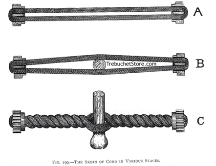
Figure 199. Catapult
- Skein of Cord in Various Stages.
|
We will now conclude that our catapult is ready for its skein of cord,
its winches being in position one on each side of the framework.
In the first catapult I made I fitted a skein of thick rope for the
arm to work between, but I found it was impossible to put an even strain
upon the rope when twisting it up with the winches.
The result of this uneven strain was, that the lengths of rope which
formed the catapult skein, each 1 1/2 in. thick, broke one by one
like rotten thread, owing to the force applied by the winches affecting
them in detail instead of collectively.
After a series of catapult experiments with various kinds of cordage,
I discovered that the finer the cord used within reason, the more elastic
and compact was the skein and hence the less its liability to break. The
fracture of a few strands of a large skein of fine cord is of no consequence,
but the breaking of one stout rope amid a skein of a dozen lengths of such
rope, means a noticeable loss of power. The ancients were well aware of
this and made the skeins of their catapults of thin cords of twisted hair.
In cases of emergency, woman's hair was made into skeins for catapults
and balistas, and of all material nothing was so elastic or enduring for
this purpose. When the inhabitants of Carthage commenced the heroic defense
of their city (149-146 B.C.) they were forced to hurriedly manufacture
weapons of all kinds to replace those which they had recently surrendered
to the Roman general Censorinus. In various modern works we read of how
the noble matrons of Carthage cut off their long tresses and twisted them
into ropes for catapults.
At the siege of Salona by Marcus Octavius, one of Pompey's generals,
the Roman women cut off their hair that it might be made into ropes for
the catapults of the besieged.
I can find no authority for any such picturesque writing, as ancient
authors simply record the fact ' that women's hair was used for catapults
at Carthage. 'For instance, Florus, in his Roman History, a chronicler
who flourished early in the second century, writes ' and the women parted
with their hair to make cordage for the catapults. 'Zonaras, Byzantine
historian, Chronica, ix. 26, says ' for the ropes of the catapults they
used the hair of the women.'
If horsehair were not available in sufficient quantity, sinews from
the necks of horses or oxen were used. I do not find that ordinary rope
was ever employed to build a catapult skein. The elasticity of hair is
so great, that however tight a large skein of it is twisted its extreme
stretching or breaking limit cannot well be reached. for this reason, there
is always sufficient life or spring in the most tightly twisted skein of
horse hair to give the requisite velocity to the arm of the catapult.
It is evident that if the skein of a catapult were twisted up to its
extreme limit, it would break under the further strain entailed on it by
winding down the catapult arm.
After testing every kind of material for the skein of a catapult I find
that horse-hair rope - 1/2 in. thick - is far the best. Failing horse-hair,
pure flax in the form of sail maker's sewing twine is a fairly good substitute.If
this twine is used for the skein of a catapult it should be spun into a
cord 1/4 in. thick.
How to Make a Catapult Skein
and
Fit It To The Catapult Arm and Frame
Insert a thin stick into the ground halfway between the winches. Place
it upright inside the framework of the catapult. This stick will serve
to keep the halves of the skein separate as it is being made, so that when
it is completed the arm of the catapult may be placed in position without
difficulty. Turn the winches till both their crossbars are perpendicular
to the ground and in line with the stick.
Next secure one end of the cord you are using for the skein to the corner
of the cross-bar of one of the winches.
Pass the other end of the cord through the holes in the sides of the
catapult and round the cross-bar of the opposite winch, and then back again
over the bar of the first winch. Do this in regular rotation to and fro,
first on one side of the stick then on the other. Be careful not to cross
the lengths of cord as you pass them between the winches, but keep them
individually straight, tight and regular and alternately on either side
of the stick, A, figure 199.
Do not wrap the cord at haphazard round the cross-bars of the winches,
but lay the turns regularly from one end of each cross-bar to its other
end and then back again.
When a complete layer of cord is wrapped over a cross-bar, place on
it a strip of paper 1 in. wide. By concealing the last layer the paper
will show you how to proceed with the next. The last few turns of the cord
will have to be passed through the winches by the aid of a piece of stout
wire with a loop at its end.
The stick may now be removed and the butt end of the arm placed between
the halves of the skein. The catapult skein should appear as in B,
figure 199.
If the skein is formed of hemp or flax and not of horse hair, the material
should be previously soaked in neat's foot oil. The oil will preserve the
skein and save it from wear and tear; it will also make the skein into
one solid mass, so that when it is twisted up by the catapult winches its
strands receive an equal strain.
When a skein is made of fine cord, it will be necessary to wrap this
(in forty yard lengths) on a number of large netting needles, such as herring
net makers use. It would be out of the question to pass and repass fine
cord in one length through the winches. My largest catapult, for instance,
required 1,400 yards of cord to make its skein.
When short lengths of fine cord are used, they will have to be knotted
together as occasion requires during the process of making the skein.
After the skein is finished and the arm of the catapult has been placed
in position therein, the former may be twisted (C, figure 199).
For this purpose a heavy spanner, 6 ft. long, is necessary.
The eye of the spanner is fitted over the squared spindle (D,
figure 193) of one of the winches. By means of the spanner, three or four
men turn one winch slightly. They then remove the spanner and go round
to the opposite side of the catapult and give the other winch a turn.
Numerals may be painted on the large wheels of the winches, so that
it may be readily seen if the same number of revolutions are given to each
wheel. This is important, as if one winch is turned more than the other
the skein will be more tightly twisted on one side of the catapult arm
than it is on the other, and a Joss of power will ensue.
The winches should be employed to twist up the skein gradually, till
it is impossible for three strong men (without the aid of the windlass)
to pull the catapult arm back, even a quarter of an inch, from the top
cross-bar against which it presses.
Three complete revolutions of the large wheel of each winch should be
sufficient to create this amount of pressure. The winches are, of course,
always turned in the same direction.
The Slip Hook Used in Ancient Large Catapult Design
|

Figure 200. Catapult
- Slip Hook Used for the
Catapult Release Trigger
|
A ringbolt of wrought iron was secured through the arm of the catapult,
just below the part of it which held the stone, figures 194 and 200. Its
lever or handle is 10 in. long. The point of the hook, which is in the
eye of the bolt, is 1 in. thick.
A stout iron slip hook was then attached to the rope that wound down
the catapult arm. The bend of the rope passed through the ring of the slip
hook. The point of the slip hook was hitched inside the eye of the bolt
and projected about 1 in. through it, figure 200.
By pulling the cord attached to the lever of the slip hook, the point
of the latter instantly slipped out of the eye of the bolt and in this
way released the catapult arm.
The point of the hook should be short and slightly tapered to its extremity,
or it will not easily slip out when required to do so. For the same reason
the point of the hook and the inside of the eye of the bolt should be smooth
and round.
However great the strain on the slip hook it will, if properly made,
easily effect the release of the catapult arm.
This simple method of releasing the arm of a catapult was far the best
as the hook that pulled down the arm was also the means of setting it free.
The slip hook was able to release the arm at any angle, whether it was
fully (as in figure 200) or only partially wound down. The trajectory of
the weapon was, therefore, controlled by this form of release, as the longer
the distance the arm was pulled down the higher the angle at which the
projectile was thrown.
On the other hand, the shorter the distance the arm was drawn back the
lower the trajectory of its missile. If, for instance, a town was being
bombarded by a catapult, the arm was wound down to its full extent of 90
degrees so that the stone it cast might strike the defenders on the ramparts,
or else travel high over the defenses and fall upon the houses and people
inside the walls.
If, however, the besiegers were threatened by a sortie from the gateway
of a fortress, the arm of the catapult was set free at a point which was
about a quarter less than its full sweep.Though the force of the missile
projected by the catapult was then, less than when its arm was fully extended
before it was released, the stone traveled low, and bounding along the
surface of the ground was more likely to encounter an enemy advancing on
horseback or on foot.
The Metal Catapult Trigger Used for Holding
and
Releasing the Arm of a Smaller Ancient Catapult
In this case the arm of the catapult was wound down to its full extent
and could only be set free from this position; hence when the catapult
was on level ground the trajectory of its stone did not vary.
To alter the trajectory of the stone thrown by a catapult of this description,
the framework of the engine was elevated or depressed, figure 192. If it
was desired to throw a stone at a low trajectory, the after end of the
catapult was raised and wedges were inserted under the ends of its sides.
|
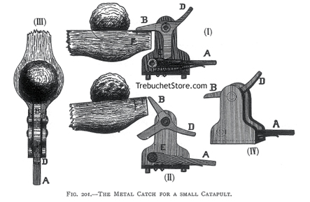
Figure 201. Catapult
- Metal Catapult Trigger
|
I - The end of the catapult arm (F) is held from escaping
by the projection (B) of the hinged catch (D). Knocking
the end of the lever (A) with a mallet, releases the leg of
the catch (E).
II - The catch then rotates, releasing the catapult arm (F).
III - Surface view of the catch holding the catapult arm.
IV - Perspective view of the catch.
If a high trajectory was required, as when as it was wished to drop
a stone into a town on an eminence, the front part of the catapult was
propped up. Even in the case of the release described in figure 200, this
was also necessary when a fortress was built on ground considerably above
the level of the catapults attacking it.
Description and Operation of the Small Catapult Trigger
Mechanism (Figure 201)
(I) F. The end of the arm of the catapult as held from
escaping by the projection B, of the hinged catch D, B.
By knocking down with a mallet the end of the lever A, the leg
of the catch (D, B), is freed from the notch in A,
at E.
(II) The catch (D, B), being then free to swing,
the end (F) of the arm of the catapult is instantly released from
the projection B, as seen in II, figure 201. This figure
may also be taken to represent the catapult arm being wound down by the
rope and roller.
When the arm is a little lower than shown in II (taking it as
coming slowly down and not as flying up), then by lifting the handle (D)
of the catch its projection (B) drops over the end (F) of
the arm. The leg of the catch at the same time snaps into the notch of
the lever A, at E. In this way the catch is reset and the
arm again secured, as in I figure 201.
(III) Plan view of the catch holding down the catapult
arm.
(IV) Perspective view of the catch.
The iron framework of the catch was bolted to a cross-piece of wood
which connected the aft ends of the sides of the catapult.
The roller that wound down the arm was fitted on the front side of this
cross piece, as shown in the catapult in figure 198.
Figure 198 is a drawing depicting a catapult for discharging stones
and javelins, but an impossible engine in most respects. It is shown only
to illustrate the roller for winding down the catapult arm.
In figure 198 there is a grooved piece of wood (in the form of
a shallow trough) on the top of the catapult. This trough is intended to
hold the javelin, the projecting butt end of which is supposed to be struck
by the released arm of the catapult. I do not believe the catapult was
ever employed to project a javelin. It certainly could not do so in the
manner here depicted, for the reason that the arm of the catapult could
never strike a true blow. Besides this, the arm of the catapult casts a
stone with a slinging motion and does not recoil with the quick snap of
a spring, such as would be necessary to flip a javelin forward .
In addition, the winches for winding the skein of cordage are put in
the weakest part of its framework in this catapult, i.e. between the uprights
in stead of the sides where they should be.
The rope attached to the roller was hitched by a hook to a ring lashed
to the catapult arm, figure 198. When the arm was safely secured by the
catch, the rope that pulled it down was unhooked and the catapult was ready
for action.
In some catapults, one end of the rope which pulled down the arm was
spliced to a crossbar of metal fixed in the framework of the siege engine;
its other end being fastened to the winding roller, figure 198. This arrangement,
using mechanical advantage, halved the exertion required to pull down the
arm and also halved the strain upon the roller, but it doubled the time
occupied in winding back the catapult arm. By using longer levers for turning
the roller, the same effect is produced as in the above method and without
the loss of time it entailed.
|
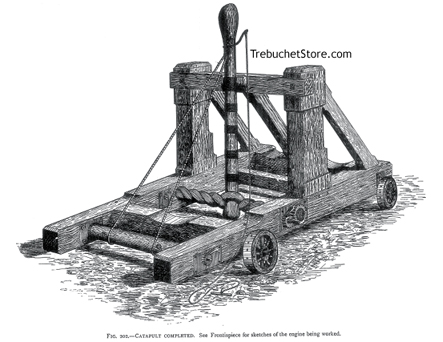
Figure 202. Completed Catapult
Built From These Plans
Build This Catapult
|
| Range of the Catapult
When its skein of cord is tightly twisted, the catapult I have described
will hurl a round stone weighing 10 lbs. to a distance of about 350 yards.
Though this is a trivial range when compared with the result obtainable
from a small mortar, it would be a more or less effective one in the days,
for example, of the Crusades , in days when the besiegers camped within
a quarter of a mile of the town they were attacking and even conversed
with the defenders on its walls.
This catapult might easily be fitted with a pair of winches each larger
by half than I have given in the plans. This would entail a stronger and
slightly longer arm, and also heavier sides to the framework of the catapult.
With these alterations, the catapult would cast a stone weighing 20 lbs.
The stones thrown by catapults do not increase in weight in proportion
to the increase in diameter of the skeins of the catapult. For example,
a catapult with a skein 1 ft. thick will throw a stone three times as heavy
as will a catapult with a skein half the size, or 6 in. A skein of 1 ft.
in thickness would, however, be double the length of the skein, which was
only 6 in. in diameter, as in the former case the framework of the catapult
would be much wider than in the latter one.
The great Roman catapult was about twice the size in length and breadth
of the one I have given a detailed plan for. This immense and powerful
machine had an arm of from 10 to 12 ft. long. A catapult of these dimensions
,according to the size of its skein , threw a stone of from 40 to 60 lbs.
to a distance of from 350 to 400 yards, the most powerful catapult of the
kind being probably able to attain a range of nearly 450 yards.
The velocity of the stone propelled by a catapult was very low as compared
with that of a ball from a cannon. It was the ponderous nature of the projectile
and not its velocity that did the execution. A stone of 50 lbs., falling
from a short range on battlements and the tops of towers, or among crowded
troops and lightly built houses, would be as destructive as a ball of half
the weight fired from a cannon at a much longer distance than was possible
with a catapult.
The damage to buildings and the slaughter of people must have been terrible,
when we consider that 150 to 200 great catapults were often employed at
the same time for pounding a city and its defenders, and further, that
these engines could be used as freely on the darkest night as by daylight.
Not only were heavy stones thrown among the besieged, their fortifications
and their houses, but flaming projectiles were also used which set fire
to everything combustible upon which they fell.
Each side of a large catapult was made of two huge logs of wood. The
logs were squared and then placed one above the other and bolted together.
Winches suitable for twisting a skein of cord such as a 10 to 12 ft. arm
required - would necessitate timber of so great a size, that the ancients
found it easier to construct the sides of their largest catapults of two
longitudinal pieces.
The skein of cord for a catapult with an arm 12 ft. in length, was much
larger in proportion to the size of the engine than was the case with a
weapon that had a framework of half the dimensions. The catapult with an
arm 10 to 12 ft. in length, also cast a stone three times as heavy as that
thrown by a weapon half its size. |
Tabletop Mangonel
Catapult Plans
|

Plan # MP1 |
 Payment Information
 |
|
U.S. Orders Only |
$12.95
Free Shipping |
|
 Build
your own Roman Mangonel with TrebuchetStore.com detailed, easy to follow
plans and instructions. When built, this Catapult stands 10"
inches tall in the fired position and will throw a scale projectile
up to 40 feet. Build
your own Roman Mangonel with TrebuchetStore.com detailed, easy to follow
plans and instructions. When built, this Catapult stands 10"
inches tall in the fired position and will throw a scale projectile
up to 40 feet.
The predecessor to the sling equipped Onager, the Mangonel could throw
huge stones and clusters of rocks, baked in clay over walls and into enemy
fortifications.
This easy to build classic torsion catapult model uses common, inexpensive
and easy to find building materials, all available at your local home improvement
store.
This complete plans package includes a shopping list of materials,
measured drawings for all parts, step-by-step assembly drawings and instructions,
as well as firing and tuning instructions.
|
Click on the images below for additional Roman Mangonel
views.
 
|
|
Save up to 50% with Multi-Plan Deals
|
| 2 Plans $19.95 FREE Shipping
- Save Over 30%
U.S. Orders Only |
|
| Do It Yourself Working Model Trebuchet Kit |
|
 Trebuchet
Kit
Trebuchet
Kit
Item #TK
|
$75.00
Free
Shipping
U.S. Orders Only |

|
The trebuchet kit includes fully precut and drilled
frame parts, pins and axles, sling cord and sewn pouch, projectiles and
fully illustrated assembly and firing instructions.
Unlike the flimsy, snap together plywood trebuchet
kits, this all hardwood trebuchet kit does not require additional cutting,
trimming or shaping.
This DIY Trebuchet Kit requires only white carpenter's
glue and a few bar clamps (not included) to assemble.
Read More
> |
| Fully Assembled Working Model Trebuchet |
|
daVinci Trebuchet
Item # T4
|
$299.00
Free
Shipping
U.S. Orders Only
|
|
Inspired by the great war machines and siege catapults of Leonardo da Vinci
, this all Red Oak
hardwood trebuchet features
an open counterweight cabinet for range and trajectory adjustment.
Fire with an empty counterweight for indoor use, or add weight (nuts,
bolts, scrap lead, iron or steel, sand, or small rocks not included) for
increased range.
Individually crafted from cabinet-grade red oak, the da Vinci Trebuchet
stands 14 inches tall in the cocked position, 24 inches tall in the fired
position and will hurl a projectile up to 60 feet. Includes six projectiles
and fully illustrated instructions.
Read More > |
Catapult - Build
a Catapult - Catapult Design Plans |