Free Crossbow Plans
Free Plans for Building an Authentic 15th Century Crossbow
The construction of a powerful crossbow, as was
used in the fifteenth century with a heavy, non-poisonous bolt. The same
crossbow, of slightly larger size, was employed in warfare from about 1370
to about 1490, when military crossbows were generally replaced by handguns.
From The Crossbow,
Construction
of a Powerful Crossbow by Sir Ralph Payne-Gallwey
The Stock
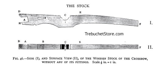
Figure. 46. - Side (I), and Surface View (II), of the Wooden
Stock of the Crossbow, without Fittings.
A. The opening to take the steel bow. The depth of this opening exactly
fits the width of the bow at its center, and is 2 in. long and 1 5/8 in.
deep. The opening is sloped upward so as to give the bow a slight cant
up, which, together with the upward curve of the ends of the bow, enables
the crossbow string to slide, without friction, along the bolt groove on
the top of the crossbow stock.
B. The oblong hole is 1 3/4 in. long and 1/2 in. wide and holds the
metal wedges (Figs. 62, 63) that secure the bow tight to the stock. The
distance between this hole and the opening for the bow at A, is 3 in.
C. The hollow, cut transversely through the stock, for the revolving
nut and its socket (Fig. 53).
The dimensions of the crossbow stock are:
Overall Length, D to F, 3 ft.
Depth Front, D to H, 3 1/4 in.
Depth Back F, 1 3/4 in.
Thickness, 1 1/2 in. from D to E, tapering to 1 1/4 in. at the Back
F.
From the Front, D, to the center of the opening at C (axle of
the revolving nut, 14 in.
The stock of a crossbow is cut from close and straight grain hardwood,
such as beech with the grain, running lengthwise for strength.
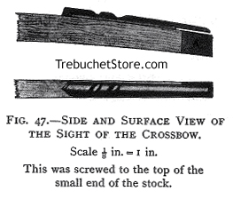
Figure 47. - Side and Surface View of the Sight of the Crossbow.
The sight is screwed to the top of the end of the crossbow stock
The sighting arrangement of a Medieval crossbow is quick and effective
. It consists of a strip of wood the same thickness as the stock, and is
1 ft. in length and 3/4 in. high (Fig. 47). The top of the strip is rounded,
and has two or three large sloped transverse notches of varied depths (Fig.
47).
The crossbowman grasped the trigger and the handled of the stock of
his crossbow with his right hand and took aim, over the sharp point
formed by the joint of the bent thumb, as it rested across one of the notches
in the wooden strip. The first joint of the thumb and the uppermost edge
of the head of the bolt, laying in the groove of the stock, gave the alignment.
When the soldier was on the march with his crossbow over his shoulder,
these notches allowed a firm grip for the fingers of one hand.
The head of the bolt, whether blunt or pointed, was usually four-sided,
with four longitudinal edges. One of these edges was always arranged to
be upright to act as a foresight when the butt of the bolt was placed between
the fingers of the nut and against the bowstring.
Being of different depths, the notches in the strip of wood along the
thumb of the right hand, acting as a backlight, could be placed higher
or lower, according to the trajectory required.
The aft end of the sighting strip (Fig. 47) is cut away for a length
of 3 in. and a depth of 1/4 in. This allows the sheath of the windlass
to be fitted over the end of the crossbow stock (Fig. 73, upper plan).
The end of crossbow stock is covered with a cap of thin metal for a
length of 2 in. to protect it from the friction of the windlass sheath,
A (Fig. 4)..
For crossbows with long stocks, such as those bent with a windlass and
its ropes, the small or pointed end of the stock (known as the tiller)
was either squeezed tight inside the right armpit, or was rested for a
few inches on the top of the right shoulder. The left hand grasped the
enlarged part of the under surface of the stock, and the left elbow rested
on the left hip or against the left side, in order to support the crossbow
in a horizontal position. The fingers of the right hand were free to work
the trigger, and the right thumb to act as a backlight The face was inclined
over the stock, bringing the right eye in line with the groove and bolt
(Fig. 36).
Louis XI. of France, 1461-1483, issued a military order that crossbowmen
in his army should have the visors of their helmets cut away on the right
side opposite the cheek, so that the visor would not interfere with the
stock of the crossbow when the crossbowman was taking aim.
The Revolving Nut and Its Socket
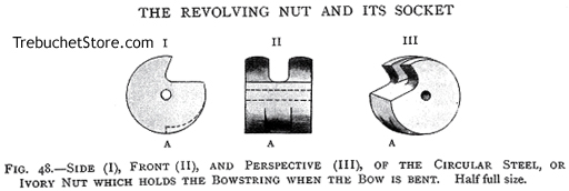
Figure. 48. - Side (I), Front (II), and Perspective (III), of the Circular
Steel,
or Ivory Nut which holds the Bowstring when the Bow is Bent.
The notch A, in the nut, is exactly below - i.e. opposite to - the curved
fingers which hold the bow-string.
The notch is 1/2 in. wide, and 1/8 in. deep on its squared face where
it engages the point of the trigger inside the stock.
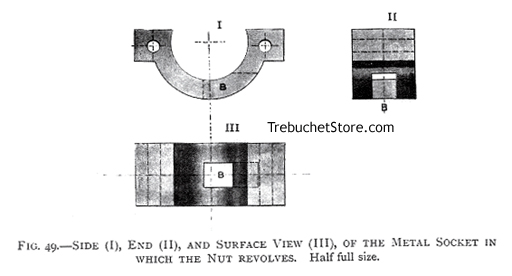
Figure. 49. - Side (I), End (II), and Surface View (III) of the
Metal Socket in which the Nut Revolves.
The longitudinal opening B is 1/2 in. wide and is cut through the under
side of the socket to allow the point of the trigger to reach and engage
the notch in the nut, as shown in Fig. 55.
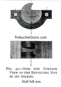
Figure 50. - Side and Surface View of the Revolving
Nut in Its Socket.
The nut and its socket should be of steel and the nut must revolve accurately
and closely in its socket. The nut is 1 1/2 in. in diameter and 1 1/4 in.
thick. The socket, in which it revolves, is 1/4 in. more than a half
circle, so as to bring the center hole of the nut 1/4 in. below the
surface of the socket, and also of the stock of the crossbow, as shown
in Fig. 50. The position of the center hole prevents the pin which passes
through the nut from being too near the upper edge of the stock. It also
gives the revolving nut more 'center bearing' against its socket to withstand
the strain of the bowstring.
The pin is 1/8 in. diameter and passes through the 3/16 in. hole
in the center of the nut and the lock plates.
The socket should take all the pressure of the nut when the bow-string
is stretched over the fingers nut. For this reason, the pin is slightly
smaller than the hole in the center of the nut. If any strain any the pin
would bend it and the nut would not revolve.
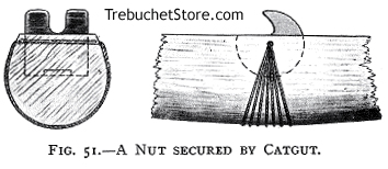
Figure. 51. - A Nut Secured by Catgut.
In many Medieval crossbows, the nut was replaced with thin length of
catgut passed several times through the hole in the nut, and then round
the stock to prevent the nut from falling out of its socket (Fig. 51.)
More often, however, the nut was held in its socket by two small screw
pins, one through each lock plate, neither of which penetrated the the
nut more than 1/4 in. (Fig. 52).
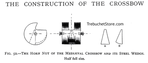
Figure 52. - The Horn Nut of the Medieval Crossbow and Its Steel Wedge.
The nut and its socket were formerly both made of horn. Steel nuts and
sockets were not generally fitted to crossbows until about 1640-1650. The
nut was usually cut from the crown of a stag's antlers. This was a strong
and light material that was free and quick in use and loose in its connection
with the bowstring. In Scandinavia, walrus tusk was commonly used for the
nut of a crossbow. The horn nut always had its notch protected by a small
wedge of hardened steel, which met the point of the trigger inside the
stock. Fig. 52 shows this kind of nut, and A, B, the front and side view
of its steel wedge separate from it.
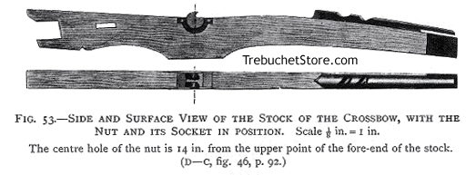
Figure. 53. Side and Surface View of the Stock of the Crossbow
with the Nut and Its Socket in Position.
The center hole of the nut is 14 in. from the upper point of the fore
end of the stock (D - C, Fig. 46).
The Trigger and Lock
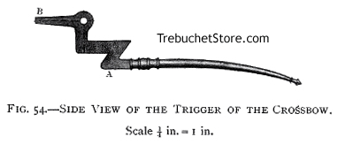
Figure. 54. - Side View of the Trigger of the Crossbow
Fig. 54. - The handle or round part of the trigger, A-A, the outside
the stock, is 8 1/4 in. long and 3/8 in. diameter. The flat part of the
trigger, A B, which works inside the stock, is 7/16 in. thick. The hole
for the transverse pin on which the trigger hinges, is 3/8 in. diameter.
The point, B, of the trigger, or the part of it which engages the notch
in the nut, is hardened to withstand wear from friction.
The point, B, of the trigger, is 7/16 in. thick and 1/4 in. deep. It
should just fit through the opening in the socket, plus 1/8 in.,
or half its depth, into the notch in the nut, as shown in Fig. 55.
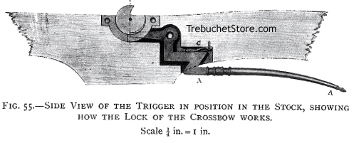
Figure. 55 - Side View of the Trigger in Position in the Stock,
Showing How the Lock of the Crossbow Works.
Fig. 55. - When the handle end of the trigger, A-A, is pressed upwards
towards the under side of the stock, the point of the trigger (B, Fig.
54), drops out of the notch in the nut. The nut, now being free to revolve,
releases the bowstring, which was stretched and previously held fast over
its fingers.
The small spring (C, Fig. 55), inside the stock, forces the point, B,
of the trigger firmly into the notch of the nut. In this way the bowstring
is securely held until the nut is released by pressing the handle of the
trigger upwards.
After the fifteenth century, other forms of trigger were invented for
holding and releasing the revolving nut. The lock described here was the
simplest and best for ordinary use and, until the end of the fifteenth
century, was the only one applied to crossbows, whether military or sporting,
which discharged bolts.
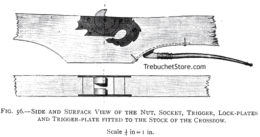
Figure. 56. - Side and Surface View of the Nut, Socket, Trigger,
Lock Plates, and Trigger Plate Fitted to the Stock of the Crossbow.
Fig. 56. The lock plates - one on each side of the stock - are of steel,
1/8 in. thick. The lock plates and their transverse screws hold the nut,
socket and trigger in position and strengthen the stock where it is cut
out for the nut and its socket.
The lock plates (shaded) are mortised in flush
with the woodwork of the stock, and close against the sides of the revolving
nut and its socket (Fig. 56.).
The trigger plate is fitted beneath the stock, as per the dotted line
and screws.
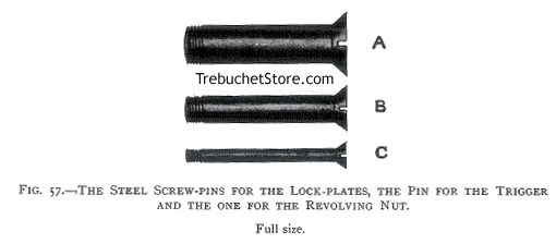
Figure. 57. - The Steel Screw Pins for the Lock Plates,
the Pin for the Trigger and the One for the Revolving Nut.
A. The 3/8 in. pin on which the crossbow trigger hinges.
B. The 1/4 in. pins (5), which fasten the lock plates and socket for
the nut.
C. The 1/8 in. pin on which the nut revolves.
These pins all pass fully through the lock plates and the stock, securing
the lock of the crossbow to its stock. When the pins are screwed into place,
their heads and points should be level with the the lock plates.
In Medieval crossbows, the pins of the lock were always riveted by a
hammer at each of their ends after they were driven in. This was, perhaps,
a tighter method of fixing them, but was a plan which prevented the lock
from being readily taken apart.
The Steel Bow, Bow Irons and Stirrup
The Bow
Dimensions of the Bow (Fig. 58)
Length - 2 ft. 6 in.
Width - At center of length, 1 5/8 in., with a gradual reduction to
a width of 1 in. at 2 in. from each end.
Thickness - At center of length, 1/2 in., with a gradual reduction to
3/8 in. at 2 in. from each end. Width across enlarged parts of ends, each
1 1/2 in.
The bow is flat on all sides, with squared edges.
For the ends of the bow, into the notches for the loops of the bowstring,
see Fig. 69.
The normal bend of the bow, taken from the center of its length, inside
its curve, to the center of a thread connecting its ends, is 4 1/2 in.,
C - D, A (Fig. 58.).
B, Fig. 58, shows how the arms of the bow are slightly canted up from
its center. If a thread is held from the center of one end of the bow to
the center of its other end, as per the dotted line, it should be 1 in.
higher at its center than the upper edge of the bow, as the bow lies on
its side on a table, x- x, B (Fig. 58.).
If the bow did not have this upward cant, the bowstring would press
so hard on the top of the stock that it would be unable to propel the bolt
with proper force. The friction of the bowstring against the stock would
prevent the string from acting freely when the bow recoiled from a bent
position. All the best steel bows were made in this manner.
Many of the military crossbows had straight bows, which were merely
canted upwards in their stocks to enable their bow-strings to work freely.
However, this did not give so straight a pull and so much strain to the
bow, as the one described in (Fig. 58.).
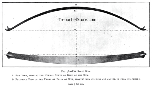
Figure 58. - The Steel Bow.
A. Side View, Showing the Normal Curve or Bend of the Bow
B. Full Face View of the Front or Belly of the Bow, Showing How Its
Ends are Canted Up from the Center
To procure a good bow of spring steel of correct size and shape, it
should be first modeled in wood. The model should then be sent to a spring
maker to copy, with instructions to temper the steel a little soft, so
that the bow may take a slight set, rather than break, if overstrained.
Bow Irons
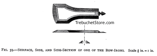
Figure. 59. - Surface, Side and Side Section of One of the Bow Irons.
There are two of these irons, one on either side of the crossbow stock.
They are each 7 in. long, 1/4 in. thick, 1/2 in. wide around their sides
1/2 in. wide between the narrow parts of their openings.
The wide openings of the irons, at their large ends are 1 5/8 in. to
fit the bow at its center. The irons surround the center of the bow, as
well as the corners of the base of the stirrup. The base of the stirrup
rests upon the center of the back of the bow. The bow irons act as straps
to pull, and hold, the bow and its stirrup tight against the stock of the
crossbow, using the metal wedges (Figs. 61, 62, 63).
When the bow, bow irons and stirrup, are in position on the stock of
the crossbow, the openings in the bow irons should each be 3/4 in. short
of the end of the oblong hole in the stock next the nut, as shown
at E, Fig. 63.
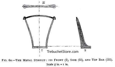
Figure. 60. - The Metal Stirrup: Its Front (I), Side (II), and Top
Bar (III).
The base of the crossbow stirrup is the same width (1 5/8 in.) as the
center of the back of the bow. Its base is 2 in. long inside, or 1/2 in.
more than the thickness of the stock, I (Fig. 60). This is necessary to
allow space for the bow irons to encircle the corners of the stirrup when
the stirrup and the bow are placed in the opening in the forehand of the
stock, before inserting the wedged (Figs. 61, 63).
The crossbowman placed his foot in the stirrup, to enable him to hold
his crossbow firmly to the ground, while he bent bow with the windlass,
or, in the case of small crossbows, as he drew the string to the nut with
his hands or by means of a rope and pulley (Fig. 77).
How to Fix the Bow to the Stock
First secure the stock of the crossbow perpendicularly in a vice, its
forehand upwards.
Take the stirrup and bow irons together, as shown in Fig. 61 and, with
center of the back of the bow being against the base of the stirrup, pass
the bow through the irons. Place the base of the stirrup and the bow in
the opening (A, Fig. 46), in the forehand of the stock, with a bow iron
on each side of the stock.
The angled ends of the short guard fit over the wood of the stock between
the sides of the bow irons. Insert the short guard, A, into the oblong
hole in the stock next to the bow (Figs. 62, 63).
Next, insert the long guard, B, through the bow irons, against their
narrow ends, and through the oblong hole in the stock (Figs. 62, 63). The
angled ends of B, turn back over the top of the solid part of the narrow
ends of the bow irons, and hold the irons close against the stock. Now
push the two wedges, C, D, in between the guards, A, B, from opposite
sides of the stock (Figs. 62, 63). By hammering in these wedges, the bow
irons will gradually draw the base of the stirrup, and with it, the center
of the bow beneath it, tight against the crossbow stock.
The empty 1/2 in. space (E, Fig. 63) of the oblong hole in the stock
is left in case further tightening of the bow is necessary. Tightening
is done by fitting a thin metal strip, to act as a washer, at the back
of one of the guards.
Before fixing the bow to the stock, ensure it is in the correct position.
For the bow to shoot accurately and with full power, requires three conditions:
I. The bow must be immovably fixed in the stock.
II. The arm of the bow on one side of the stock, should be less than
1/8 in. longer or higher than its arm on the other side of the stock. A
piece of twine tightly fastened from one end of the bow to the other, with
a little bit of colored silk knotted round the exact center of its length
is a valuable guide when regulating the position of the bow.
III. When the bow is fixed, a thread of cotton stretched from the center
of one end of the bow to the other, should be in a straight line and not
pushed up at its center by the surface of the stock.
The thread should cross 1/4 in. above the stock, so that when the bowstring,
which is 1/2 in. in diameter, is fitted to the bow, the lower edge of the
string will just lightly touch the groove in which the bolt is laid so
there will be no friction to retard the force of the bow-string when the
crossbow is discharged.
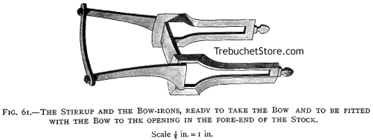
Figure 61. - The Stirrup and the Bow Irons, Ready to Take the Bow
and be Fitted with the Bow to the Opening in the Fore End of the Stock.
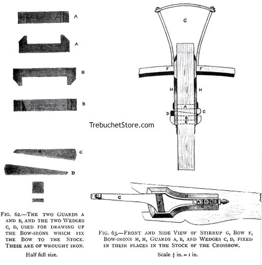
Figure 62. - The Two Guards A and B, and the Wedges C, D, Used for
Drawing
Up the Bow Irons which Fix the Bow to the Stock. These are of Wrought
Iron.
Figure 63. - Front and Side View of the Stirrup G, Bow F, Bow Irons
H, H,
Guards A, B, and Wedges C, D, Fixed in Their Places in the Stock of
the Crossbow.
The Groove for the Bolt
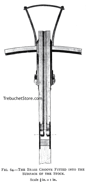
Figure 64 .- The Brass Groove Fitted Into The Surface of the Stock.
The groove (13 1/4 in. long, 3/32 in deep in its hollow) may be of brass.
It reaches from the forehand of the crossbow stock to the metal socket
which holds the revolving nut (Fig. 64.).
The short (3/4 in.) length of the section of the metal socket
which is in front of the nut, is recessed to correspond with the long separate
grooved piece which comes up to it (Fig. 64.).
The groove should be neatly and tightly mortised in flush with the surface
of the stock (Fig. 65.). It should have two, or three thin pins to secure
it from slipping forward, and will have to be as smooth as glass and as
true as a gun barrel from end to end.
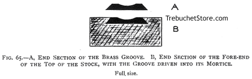
Figure 65. - A, End Section of the Brass Groove. B, End Section of
the
Fore End of the Top of the Stock, with the Groove Driven into Its Mortise.
In many old crossbows the groove for the bolt was of horn, and glued
into its mortise on the top of the stock. This was a lighter method and
is one to be recommended if a suitable piece of horn is available.
The Crossbow String
The crossbow string should be composed of several dozen turns of thin
twine, of pure hemp or flax. Sailmakers sewing twine is excellent for the
strings of large crossbows, as it is very strong and will not stretch under
the great strain of the steel bow. Any twine in the form of soft twisted
string is sure to stretch and, what was at first a taut bow string will,
if this kind of material is used, soon become slack and useless.
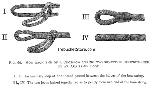
Figure 66. - How Each End of a Crossbow String was Sometimes
Lengthened by an Auxiliary Loop.
I, II An auxiliary loop of fine thread passes between the halves
of the bowstring.
III, IV The two loops lashed together so as to jointly form one
end of the bowstring.
In some Medieval crossbows, the bow-strings were strengthened at their
ends in a very ingenious manner by means of auxiliary loops. How this was
done is shown in Fig. 66.
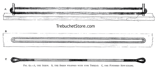
Figure 67. - A, The Skein. B, The Skein Wrapped with Fine Thread. C,
The Finished Bow-String.
How to Make the Bow-String of a Crossbow which Shoots Bolts (Fig. 67).
Hammer a round peg of hard wood (4 in. long, 1/2 in. diameter) firmly
into a hole drilled through a board 3 ft. in length, by 6 in. wide
and 1 in. thick. The hole for the peg should be 3 in. from one end of the
board, and the peg should be set perfectly upright.
Place the notch at one end of the steel bow level with this peg, then
fix a second peg in the board 1/2 in. short of the notch at the other
end of the bow. The measurements should be taken from the outside edges
of the pegs. This will give you the correct length of the bow-string.
Next, wind the fine twine evenly round and round the two pegs in the
board, being careful not to cross the threads between the pegs until you
have a smooth tight skein (A, Fig. 67). Continue wrapping the skein halves
together until, when piece of twine, wrapped around the center inch of
the skein, results in pulling the skein to a diameter of 1/2 in.
Now rub beeswax all over the skein until its threads stick together.
This will make the bow-string impervious to water or damp and will preserve
it indefinitely.
Without removing the skein from the pegs, wrap a long well waxed length
of strong silk - in turns 1/8 in. apart around its entire length, and a
little closer (by the aid of a darning needle) at its ends where they pass
round the pegs (B, Fig. 67). Without this wrapping, the skein is sure to
fail (especially at its ends), into a hopeless tangle during the process
of converting it into the bow-string.
Using some hard twine, tightly wrap the skein (or bowstring as it may
now be called), as shown in C, Fig. 67.
The center wrapping, which lies above the groove in the stock, is 4
in. long and the end wrappings are each 3 in. long. The center wrapping
may be overlaid at its center, for 1 in., with a little crimson silk, to
show the exact center of the bow-string, so should the bow shift in use,
the movement can be detected and the bow re-adjusted in the crossbow stock.
The loops at each end of the bow-string should be wrapped, if possible,
without removing the skein from the pegs in the board. If this cannot be
achieved, on no account lift the skein off the pegs till the center and
end wrappings are completed.
When the bow-string is finished, the silk can be removed where it shows
between the wrappings.
How to Fit the Bow-String to the Bow
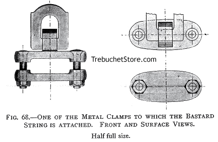
Figure 68. - One of the Metal Clamps to which the Bastard String
is Attached. Front and Surface Views.
The bow-string is 1/2 in. shorter than the space between the notches
of the bow and will not reach from one notch of the bow to the other. Otherwise,
the bow-string would not be taut when the bow is strung.
To place the loops of the bow-string over the notches in the ends of
the bow, mechanical aid is necessary. It would be quite difficult to bend
a thick steel bow for this purpose by manual power alone.
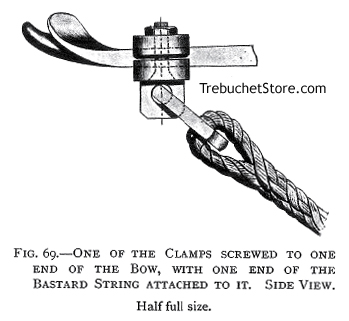
Figure. 69. - One of the Clamps Screwed to One of end of the Bow,
with One End of the Bastard String Attached to It.
To fit the bow-string to a crossbow, use a bastard string The bastard
string - by means of the windlass of the crossbow (Fig. 76) - bends the
steel bow sufficiently to allow the loops of the bow-string to be slipped
into the notches at the ends of the bow (Fig. 70.).
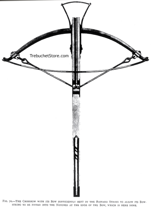
Figure 70. - The Crossbow with Its Bow Sufficiently Bent by the Bastard
String to Allow
Its Bowstring to be Fitted into the Notches at the End of the Bow.
The bastard string is then removed from the bow (Fig. 71.).
The bastard string (constructed similar to the bow-string) is temporarily
fixed to the arms of the steel bow by two small iron screw clamps (Fig.
70.). It hung loosely when the clamps are attached near the ends of the
bow. The windlass is used to pull the bastard string tight down over the
fingers of the nut, and held while the bow-string is fitted (Fig. 70.).
By regulating the position of the clamps on the bow, any crossbow
can be bent by its windlass just enough to remove and replace the
bow-string.
To remove the bastard string (after having fitted the bowstring into
the notches of the bow), do not pull the trigger of the crossbow. Hold
one handle of the windlass with one hand and press the trigger at the same
time with your other hand, then let the bastard string gradually slacken
and the bowstring tighten as you reverse the windlass.
The fitted bow-string should be from 1/2 in. to 3/4 in. further along
the groove in the stock, towards the nut, than a thread would be, if stretched
between the ends of the bow at rest prior to installing the bow string.
In this crossbow the front of the string should be 5 in. from the inside
upper edge of the center of the bow, and the back of the string, 6 in.
from the center of the nut.
If the fitted bow-string is a slack, take it off the bow by means of
the bastard string. Undo the center wrapping, give the string two or three
twists to shorten it, then replace it on the bow and wrap its center again.
If the string is too tight, and bends the bow too much, there will be
a waste of power and a risk of fracture when the bow is fully bent
by the windlass.
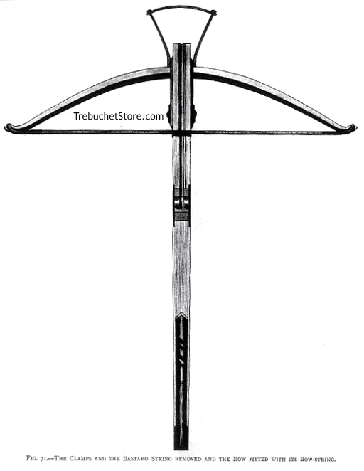
Figure 71. - The Clamps and the Bastard String Removed and the
Bow Fitted with Its Bowstring.
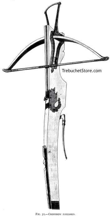
Figure 72. - Crossbow Finished.
A bow string which is 1/2 in. too long, can be set right, but a string
which is 1/2 in. too short is beyond remedy. If the bow string is too short,
unwind the skein and remake it longer.
The crossbow is now complete, with the exception of its windlass. It
should appear as in Fig. 72, with its woodwork smoothed and nicely stained,
and its metal fittings hardened and polished. The sharp edges of the stock
can all be rounded off slightly, excluding the opening in which the bow
and its stirrup are fitted.
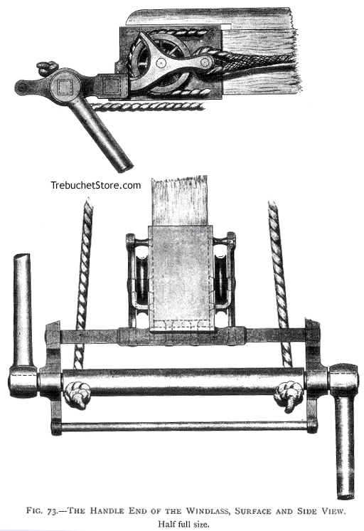
Figure. 73. - The Handle End of the Windlass : Surface and Side View.
The Crossbow Windlass
The sheath of the handle end of the windlass fits over the small end
of the stock of the crossbow, as shown in Fig. 73. In the surface view,
only the ends of the cords are inserted, to avoid confusion of detail.
The end of the sighting strip is also omitted in this view for clarity.
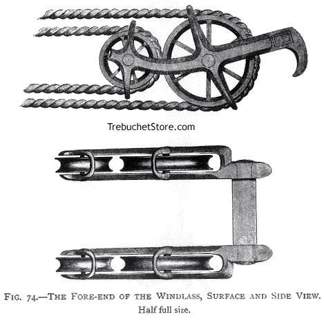
Figure. 74. - The Forehand of the Windlass Surface and Side View.
Fig. 74. In the surface view, the pulley cords are not given, in order
to show more clearly the arrangement of the wheels and of the guards which
keep the cord in position on the wheels. See Fig. 75 for the windlass in
position on the crossbow.
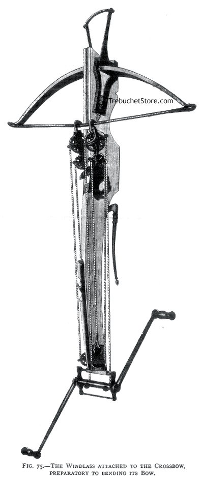
Figure 75.- The Windlass Attached to the Crossbow,
Preparatory to Bending the Bow.
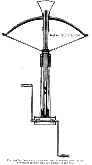
Figure 76. - The Crossbow with Its Bow Bent by the Windlass and
Its Bowstring Secured Over the Fingers of the Nut.
To draw the bow-string of a powerful crossbow to the nut, a windlass
or cranequin is necessary. Though the distance which the bow-string has
to be pulled along the top of the stock is only 5 or 6 in., no manual strength
could draw it half-way.
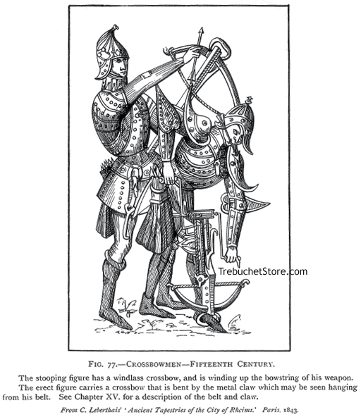
Figure 77. - Crossbowmen in Fifteenth Century.
The stooping figure has a windlass crossbow, and is winding up the bowstring
of his weapon. The erect figure carries a crossbow that is bent by the
metal claw, which may be seen hanging from his belt.
A crossbow windlass, small as is, has immense power and will draw the
bow-string to the nut smoothly, quickly, and with no perceptible strain
or exertion.
To use the windlass, the sheath of its handle end is fitted over the
small end of the stock, and the claws of its forehand are hooked over the
upper surface of the bow-string, as shown in Fig. 75.
In Fig. 76, the bow is bent, but the windlass is not removed, its showing
proper position on the stock and string .
By reversing the handles of the windlass a couple of turns to slacken
its cords, it can be quickly removed from the stock of the crossbow, which
is then ready for use. In former days the crossbowman, after he had stretched
his bow-string and removed the windlass, suspended the windless from his
side, by means of a hook attached to his belt.
Fig. 77 shows a crossbowman using his windlass to bend his steel bow.
He holds a bolt between his teeth so it is ready at hand to place
on the stock of his crossbow once its bow is bent.
The Bolt, or Quarrel, and How It was Arranged on the Stock
of the Crossbow
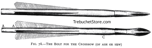
Figure. 78. - The Bolt for the Crossbow (of Ash or Yew).
Dimensions
Total Length - 12 1/2 inches.
Length of head - 3 inches
Diameter of shaft at C, near where it meets the sheath of the metal
head - 11/16 of an inch.
Height of the shaft at its butt end - 1/2 inch
The weight of the bolt is 2 1/2 oz. (shaft 1 oz., metal head 1 1/2 oz.).
The butt of the shaft, for about an inch, A - A, is slightly flattened
at opposite sides (in line with the side feathers) and then tapered to
a width of 3/8 in. (Figs. 78, 79). This allows the butt to fit between
the fingers of the nut and against the bow-string, as shown in Fig. 82.
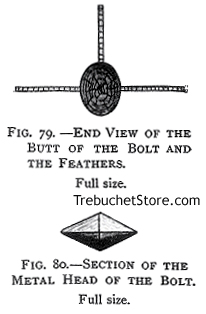
Figure 79. - End View of the Butt
of the Bolt and Feathers.
Figure 80. - Section of the
Metal Head of the Bolt.
The butt of the shaft, being tapered as well as flattened, can be gently
wedged in between the fingers of the nut to prevent the bolt from slipping
forward when the crossbow is aimed towards the ground. The head of the
bolt is greater in width than height (Fig. 80.).
The head is shaped so that it might not touch the groove of the stock,
and cause friction or divert the direction of the bolt when it is propelled
by the bow.
The bolt should lie with only the enlarged fore end of its wooden shaft
(C, Fig. 78), and its butt resting on the groove of the crossbow.
The side edges of the head of the bolt should be in line with the side
feathers of the shaft, and the upper edge of its head, - as the bolt lies
in the groove on the top of the stock, - in line with the top feather of
the shaft. One edge of the head of the bolt will be upright, to act as
a long and fine fore-sight.
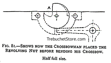
Figure 81. - Shows How the Crossbowman Placed the
Revolving Nut Before Bending His Crossbow.
Before bending his crossbow, the crossbowman revolved the fingers of
the nut downwards into its metal socket, in the direction of the bow (Fig.
81.). When the bow-string was drawn along the groove of the stock by the
windlass, it contacted the flat surface of the nut at A and rotated
the nut around into the position which caused its notch to engage the point
of the trigger inside the stock and secure the bow string behind the nut.
The bow string was held fast until the trigger was pressed to discharge
the crossbow.
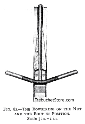
Figure 82. - The Bowstring on the Nut and the Bolt in Position.
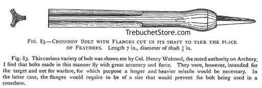
Figure. 83. - Crossbow Bolt with Flanges Cut in Its shaft to
Take the Place of Feathers. Length 7 in., diameter of shaft 1/2 in.
Figure. 83. This curious variety of bolt was shown me by Col. Henry
Walrond, the noted authority on Archery. I find that bolts made in this
manner fly with great accuracy and force. They were, however, intended
for the target and not for warfare, for which purpose a longer and heavier
missile would be necessary. In the latter case, the flanges would require
to be of a size that would prevent the bolt being used in a crossbow.
Get a restored, printable copy of these Modern
Crossbow Plans with
Enhanced and Enlarged Figures and Illustrations
and Searchable Text.
|
|
Build
and Shoot Modern Crossbows
|

|
PDF Format
|
All Orders Processed
On a Secure Server
|
|
|
|
Price $12.95
|
|
|
|
We will email your plans, to the address provided
with your payment, within 48 hours following receipt of your order.
|
10 Pages, Print Size 8.5" x 11"
|
|
Save up to 50% with Multi-Plan Deals
|
| 2 Plans $19.95 FREE Shipping
- Save Over 30%
U.S. Orders Only |
|
| Do It Yourself Working Model Trebuchet Kit |

|
 Trebuchet
Kit
Trebuchet
Kit
Item #TK
|
$75.00
Free
Shipping
U.S. Orders Only |

|
The trebuchet kit includes fully precut and drilled
frame parts, pins and axles, sling cord and sewn pouch, projectiles and
fully illustrated assembly and firing instructions.
Unlike the flimsy, snap together plywood trebuchet
kits, this all hardwood trebuchet kit does not require additional cutting,
trimming or shaping.
This DIY Trebuchet Kit requires only white carpenter's
glue and a few bar clamps (not included) to assemble.
Read More
> |
| Fully Assembled Working Model Trebuchet |
|
daVinci Trebuchet
Item # T4
|
$299.00
Free
Shipping
U.S. Orders Only
|
|
Inspired by the great war machines and siege catapults of Leonardo da Vinci
, this all Red Oak
hardwood trebuchet features
an open counterweight cabinet for range and trajectory adjustment.
Fire with an empty counterweight for indoor use, or add weight (nuts,
bolts, scrap lead, iron or steel, sand, or small rocks not included) for
increased range.
Individually crafted from cabinet-grade red oak, the da Vinci Trebuchet
stands 14 inches tall in the cocked position, 24 inches tall in the fired
position and will hurl a projectile up to 60 feet. Includes six projectiles
and fully illustrated instructions.
Read More > |
Free Crossbow Plans - Free Plans for Building an Authentic
15th Century Crossbow |