Free Shipping
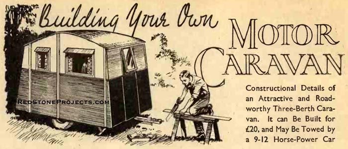
Building Your Own Motor Caravan
Vintage Plans For a Light, Easy to Tow Camp Trailer
|
Building Your Own Motor Caravan
Vintage Plans For a Light, Easy to Tow Camp Trailer
 |
PDF Format |
|
|
All Orders Processed
On a Secure Server
|
Price $12.95
|
|
Get a restored copy of these vintage Building Your
Own Motor Caravan Plans with 26 Pages of Enhanced and Enlarged
Figures and Illustrations and Searchable Text.
|
We will email these plans, to the address provided
with your payment, within 48 hours following receipt of your order.
|
|
|More
Vintage Trailer Plans|
|
|

|
|
|
|
Building Your Own Motor Caravan
|
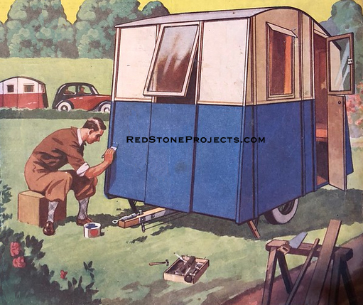
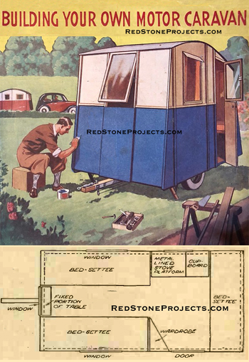
| HAVING enjoyed several very happy holidays in caravans
which had been hired on each occasion, it occurred to me early last year
that the building of a caravan of my own design would not be too difficult
a job, and would, in fact, be a somewhat intriguing way of spending leisure
moments and week-ends.
There were many points to be considered before making
a start, and the question of tools was first carefully reviewed, and it
was decided that my ordinary set - very ordinary - should meet the case,
this consisting of one household saw, one hacksaw, various chisels, spanners
and screw drivers, one small vice, one 4 -in. cramp, and all the usual
odds and ends that are accumulated by the average handyman. |
|
Constructional Details of an Attractive and Roadworthy
Three -Berth Caravan. It can Be Built for £20, and May Be Towed by
a
9-12 Horse-Power Car.
|
| Cost was naturally of considerable importance and on
rough figures it was estimated that the total should not amount to more
than about £20. Eventually it worked out a little less. Unfortunately,
there was no garage or storage place available, but the use of a large
tarpaulin seemed the only means of keeping the job clean and dry.
The Axle
The idea, after thinking over all the likely difficulties,
grew into realization and forthwith a suitable axle unit was selected from
a local car dismantler. There were so many different types and sizes of
axles to choose from that the first visit to the dismantler's was somewhat
bewildering. The points to consider were: (1) Extreme solidity; (2) Efficient
braking and easy brake operation; (3) Wheel base; (4) Spring base, that
is, distance between each spring; (5) Wheel and tire sizes.
Perhaps the spring base is of major importance, as in
view of the very considerable overall width of the caravan, the springs
should be mounted as wide apart as possible.
The average car front axle has a very narrow spring base,
apart from which there is always some difficulty in locking the swivels,
and as a scrap unit is probably in a worn condition the swivels would perhaps
be very slack.
This latter condition would naturally be very undesirable,
and for these last two reasons it was eventually decided to make use of
a rear axle assembly and one preferably with underslung springs.
The efficiency of the brakes on the average car rear axle
may, up to a point, be taken for granted, but large -diameter brake drums
are useful as the amount of effort at the brake lever is not very great.
With regard to wheel size, there is never very much choice, but an average
may be regarded as 19 in. with a low-pressure tire size 27 x 440 (or 450
x 19). |
|
|
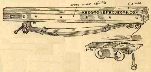
Figure. 1. Showing the hanger for the front end
of each spring, and the method of attaching the spring to the chassis.
|
| Axle Details
After a great deal of searching, I was fortunate in finding
an old Riley (which had been very badly damaged at the front of the chassis,
the rear axle, rear wheels and springs being apparently in quite sound
condition. The rear axle and springs seemed adequately to fulfill the requirements
under consideration, as the spring base was 37 in. center to center, wheel
track 4 ft. and spring camber 7 in. approximately. A few days later, when
the car was dismantled, I purchased the complete rear axle assembly, rear
wheels and springs, and then proceeded to make due alterations to adapt
the unit for use in the caravan chassis.
In doing this, the chief trouble lay in the fact of the
propeller shaft being enclosed by a long torque tube, but as the tube at
the forward end was already damaged, and in any case the propeller shaft,
bevel pinion and other parts were not required, I decided to cut the crown
gear housing short. On dismantling the differential and axle, it was found
that the brakes were in quite good condition, apart from the camshafts
being rather badly rusted, but it was not a difficult matter to put the
brakes in really very good order by cleaning and greasing the camshafts
and roughing up the brake linings.
The next step was the stripping of the differential assembly,
which was rebuilt with the crown wheel left out, only the differential
box and pinions remaining so as to provide a center bearing for both axle
shafts. The nose of the crown gear housing where it had been cut short
was blocked up with a plug of hard wood, and in finally fitting up the
cover plate a quantity of grease was put in the axle casing. The results
of this work were very gratifying, as the differential had an extremely
smooth movement, the braking seemed efficient, and the unit was undoubtedly
very solid.
Road Springs
For the time being I had to return to the work on the
axle unit, and took off the road springs for examination. Apart from being
somewhat rusty, they were quite sound and their camber seemed to be just
suitable to give clearance to a straight chassis side member. Some provision
had to be made for the axle unit to take the torque resistance when braking,
and as separate torque rod or member would only have involved extra weight
and unnecessary work, I decided to dowel the springs to the axle case,
using the existing spring dowel pins and letting down the spring platform
to grip the machined surface of the axle case. Apart from drilling the
axle case, which gave tremendous resistance to my comparatively crude tools,
there was no difficulty in doing this, although naturally great care had
to be taken in drilling the dowel positions at the exactly correct point
on the circumference of the axle case.
Making the Chassis
The undercarriage assembly having been completed, the
chassis members were prepared for fitting. The longitudinal members were
12 ft. 3 in. by 2 in. by 3 in. ash, cut to length and planed on each face,
and the cross members were also of 2 in. by 3 in. ash, 6 ft. long. Two
center longitudinal members were selected and were strengthened by bolting
to the 3 in. face, a strip of mild steel 1 1/2 in. by 3/16 in. for practically
the whole of their length. It was decided to mount the axle a little behind
center of the chassis in order to make the caravan slightly nose heavy,
and so add to its road -holding qualities. Accordingly, a point 9 in. behind
dead center of the center longitudinal members was duly marked, and the
axle offered up, thereby giving the location of the front shackle. This
was made by welding a strip of 1 1/2 in. by 3/16 in. mild steel to the
inside of an inverted spring shackle. (See Fig. 1.) |
|
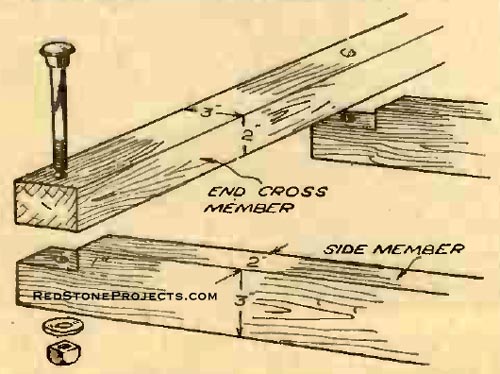
|
Figure. 2. Method of jointing used between the
ends of the chassis side members and cross members.
|
| The steel plate was drilled in three places and bolted
up to the underside of the chassis member. The rear end spring mounting
naturally had to be flexible and the spring suspended from a shackle in
a similar way to a motor - car front spring, and although the original
design incorporated the use of a car chassis shackle bracket, it was eventually
decided to bolt a 6 in. length of the strip steel previously used to the
opposite side of the chassis side member, drilling through the plating
on both sides, also the wood, to take a shackle pin carrying the top end
of the spring shackle. |
|
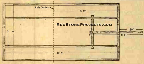
|
Figure 3. This is a plan view of the chassis frame
showing the principal dimensions.
|
| In determining the position of the top rear shackle bolt
the spring shackle was set vertically so that when the chassis was under
load there would be enough movement in a rearwards direction to provide
spring flexibility. A sketch of the spring suspension is shown in Fig.
1, both sides being identical. |
|
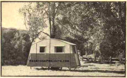
|
Figure 4. This illustration gives a good impression
of the appearance of the home-made caravan described.
|
To make up the total 6 ft. width of the chassis, two
extreme cross members were fitted back and front across the two already
assembled center members. The material used for these cross members was,
as before, 2 in. by 3 in. each, and the extremities of the center chassis
members were recessed 1 in., the cross members being carried on top of
the others and secured by 4 1/2 in. coach bolts (see Figs. 2 and 3). It
will be noted that the 3-in. face of the side member is vertical, whereas
the same face of the cross member is horizontal the extreme chassis side
members 12 ft. 3 in. and 2 in. by 3 in. each were then suspended from the
extremities of the cross members, being recessed in a similar manner to
the previous fitting. This arrangement gave all four chassis side members
an equal height, the fact being utilized when making and fitting the floor
boards, which was the next step. It would be as well to mention that before
covering the chassis, all the side members were heavily
creosoted and the undercarriage, springs and shackles well coated with
a good -quality paint. |
|
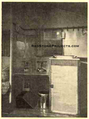
|
Figure. 5. A view of the inside of the rear compartment
showing cupboard and stove compartment.
|
| Fitting the Floor
The flooring was made of 7/16 in. tongued and grooved
weather boarding in 6 ft. lengths, each length being screwed down across
the top of each chassis side member. Special care was taken in fitting
the floor boards to strengthen the framework against twist or distortion
such as would be involved under normal road conditions. In the center of
the flooring the boards were reduced to 4 ft. width to clear the road wheels
which protruded above the height of the chassis members, leaving an aperture
30 in. by 24 in. on both sides to form a raised wheel arch which was built
later. Each length of boarding, before being finally laid down, was well
soaked in creosote, the top surface being left white so that the inside
color scheme could be decided upon later.
At a distance of 36 in. behind the extreme front cross
member and slung underneath the side members was bolted-up another cross
member to carry the back end of the trailer bar. For both trailer bar and
extra cross member, similar-sized timber was employed 2 in. by 3 in., and
the trailer bar before fitting was strengthened with a strip of 11/2 in.
wide steel bolted to its side. The trailer bar was attached to the front
of the chassis cross member by means of a 1/2 in. steel bolt with large
steel washers and a split-pinned nut, the rear end of the bar being similarly
treated.
Bodywork
In view of the necessity for minimizing the total cost
of the caravan it was decided to make use of ordinary commercial 1/8 in.
plywood which is obtainable in a stock size of 5 ft. square sheets. The
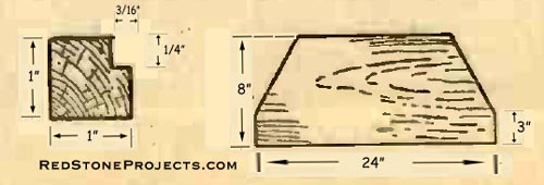
timber for the body pillars was next ordered in 7 ft. lengths of 1 1/2
in. square, rebated 1/4 in. on one face, 1/8 in. deep (see Fig. 6) for
taking the end surface of each sheet of plywood. The two front side pillars
were, however, of a stronger material, 3 in. by 1 1/2 in., and similarly
rebated, the extra strength being considered necessary to take wind resistance
and other similar forces normally met under travelling conditions. |
 |
|
Figure 6. Section of front pillars (left) and
of other body pillars (right).
|
| The front end was first assembled, and a triangular template
with an angle of 80 degrees was made so that the front corner pillars could
be set at the correct angle. The corner pillars (A) of 1 1/2 in. square
ash were cut to length, 5 ft. 2 in., and the front cross member recessed
so that when the pillar was screwed in position its angle conformed to
the template previously made. The front side pillars (B), of 3 in. by 1
1/2 in., were then fitted and bolted to the outside of the chassis side
members.
The space formed between the two pillars was filled up
with a sheet of plywood cut to shape, the bottom edge of the ply being
flush with the lower edge of the side member, and each contacting face
of the plywood glued, tacked and screwed.
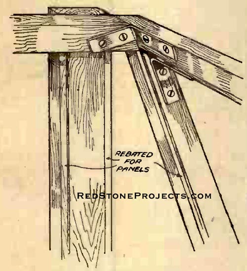
A cross rail (C) of 1 1/2 in. square ash was then fitted
on top of the extremities of the front corner pillars, steel angle brackets
being the method of attachment in addition to the pillars and rail being
screwed together. (Fig. 7.) The center front pillars were recessed into
the front cross member similarly to the corner pillars and were again joined
to the roof cross rail by screwing and the fitting of corner brackets.
At a distance of 27 in. below the roof cross rail another cross rail (D)
was fitted between the two center pillars to form the aperture for the
front window and a plywood panel was cut and fitted between this cross
rail and the front cross member (on the outside face of the pillars) and
more plywood panels were cut and fitted to fill in the apertures between
the corner and center pillars, the plywood in this case being glued and
screwed to the inside face, thereby making a small bay of the center section.
(Fig. 8.)
Starting on the offside, the center pillar E, 6 ft. 8
in. in overall length, was bolted to the side member, and a complete sheet,
5 ft. square, of plywood fitted between its one edge and the front pillar
B.
The rear pillar F was similarly fitted, but its height
was not determined until the roof side rail had been sprung in position,
which necessarily had to be done very much later. The rear corner pillars
G, and center pillar H, were fitted on similar lines to the front pillars,
and the rear door post was fitted and left an indefinite length. The front
door post and nearside center pillar were erected and the spaces between
each pillar, excepting, of course, between the door posts, were filled
with sheets of plywood.
At this stage, the whole of the woodwork now assembled
was thoroughly primed with a red lead primer, particular care being taken
in sealing the edges of the plywood, the top edges having no support or
fixing as yet.
It was next necessary to secure the top extremities of
the front B and front corner pillars A by means of a specially-made corner
bracket (Fig. 10) and on the offside a rail (see Fig. 8) of 1-in. square
ash was fitted along the top edge of each plywood panel, extending from
the front corner pillar A to the rear corner pillar G, the rail being screwed
to the inside of each pillar and the plywood being glued, tacked and screwed
to the rail. On the nearside a similar rail was fitted, but terminating
at the front corner post, a short rail being used between the rear door
post A and the corner pillar G.
Curved Side Rail
The next step was to provide a pair of curved roof side
rails, and for this purpose two 12 ft. 6 in. lengths of 1 -in. square straight-grained
ash were obtained and, using the floor of the caravan, were bent on an
improvised jig and left for several days, occasionally being soaked with
hot water. After each day of this treatment the bend was gradually increased,
so that when the timber was eventually released its curvature corresponded
very closely to that required between the corner pillars A and G and center
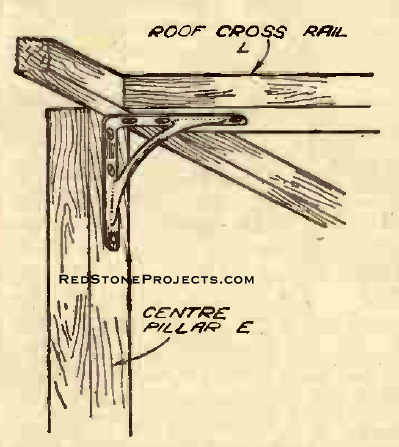
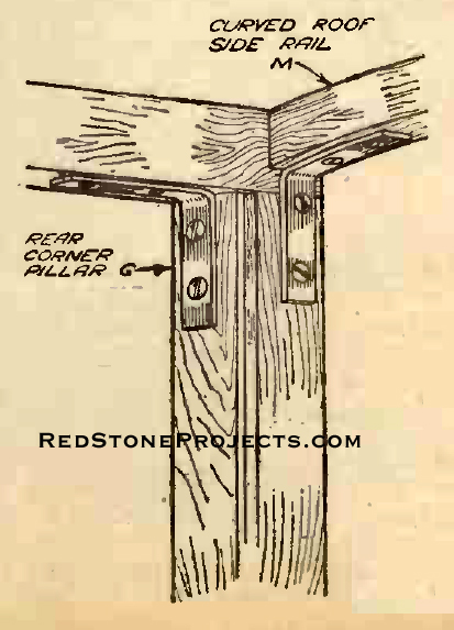
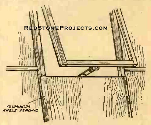
pillars E. At the top of each center pillar a 3 in. by 3 in. reinforced
angle bracket was fitted as shown in Fig. 12. It was then a comparatively
simple matter to attach the one end of the curved roof rail to the top
of the rear corner pillar (Fig. 13) and then, after straining the side
rail over the center pillar brackets, screwing it directly to the top inside
face of the main front side pillars (Fig. 10).
This operation was repeated for the opposite side and
the center roof cross rail L was screwed on to the same brackets as the
side rails, after having been cut to such a length as to give a total width
of 5 ft. 9 in. between the two outside faces of the side rails. |
|
Figure 7. Elevation view showing the members constituting
the front of the body frame.
Figure 8. Nearside of the body framework.
|
Get a restored copy of these vintage Building Your
Own Motor Caravan Plans with 26 Pages of Enhanced and Enlarged
Figures and Illustrations and Searchable Text.
|
| Paneling
It was now possible to complete the paneling of the caravan
sides and accordingly the space between the curved roof rail M and the
lower side rail J was filled in with plywood sheets, the top edges of which
were cut to fit flush with the top of the curved rail M and, incidentally,
the center panel top bracket was removed and refitted to clamp the sheeting
between itself and the pillars. Although it would have been possible to
have covered the roof framework with the waterproof material already obtained,
it was thought that the inside finish would not be very satisfactory, apart
from the obvious difficulty of fitting the material smoothly, and so it
was decided first of all to cover the roof with plywood sheets similarly
to the body sides. As the overall width of the roof was 5 ft. 9 in., a
center rail had to be fitted through the length of the roof so that the
roofing could be made in separate panels. This rail was obtained as a 12
ft. 6 in. length of ash 2 in. by 1/2 in. and was quite easily fitted, its
curvature being almost identical with that of the side rails. The extremities
were screwed directly to the roof end cross rails, and the center roof
cross rail was recessed 1/4 in as an added steady, the joint of this being
glued and screwed. The roof behind the center pillars was covered in by
two separate sheets 5 ft. in length and approximately 2 ft. 10 in., and
as two more sheets of plywood cut similarly did not entirely cover in the
front end of the roof, an extra roof cross rail was made and fitted at
the point marked N in Figs. 8 and 11. The roof covering was then completed
by filling in the two comparatively small spaces at the front.
Waterproofing the Roof
After the outside roof paneling had been thoroughly dressed
with primer, it was covered with a single piece of waterproofed hood material,
similar to that used on cars, obtainable in 6 ft. widths and in several
different colors and shades. The color scheme decided upon was two shades
of green with cream uppers, and we were fortunate in obtaining a material
of a suitable shade of green. The material was merely stretched from end
to end of the roof and then drawn from side to side, and when finally,
it was perfectly smooth all over the roof it was tacked down. The lower
edges were left for the moment, as it was thought better to allow the weather
to take effect on the material before finally cutting off and fitting the
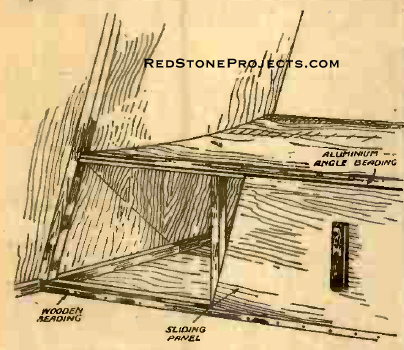
roof guttering. In order to protect the lower edge of each body panel,
angle strips of aluminum beading were fitted between the pillars and bedded
snugly against the plywood and the underside of the chassis side members,
a little putty being spread along the inside of the aluminum beading before
finally tapping down and pinning in position (see Fig. 15). This angle
beading was also used to protect the edges of the front window bay and
the edge of the plywood up each corner pillar.
The body shell being completed, the positioning of the
windows was decided upon and a window frame made for the front. For all
the windows planed deal 1 in. square rebated 1/4 in. by 3/8 in. (Fig. 16)
was used, the window frame corners being jointed in the orthodox manner.
The glass, after being cut to size, was bedded down into the window frame
with putty and secured by strip 1/4 in. round beading (Fig. 17). Similar
beading was also used as weather strip for the inside of the window aperture.
|
|
Figure 10. Method of joining the front corner
pillars.
|
Windows
Working from the inside of the caravan, the side windows
were marked out on the paneling, making a window aperture of 30 in. by
20 in. After cutting out this space with a hacksaw blade on an improvised
handle, a frame was built up around the inside, 1 in. square deal being
used and the window side pillars being jointed into the side rail. The
lower rail of the window frame was extended to the inside of the front
and center body pillars, making a waist rail above the seating position.
This rail P was screwed on to the pillars mentioned and was also pinned
and glued to the outside plywood.
A corresponding window was made to suit a similar operation
carried out on the opposite side. The offside rear window was made up on
identical lines, the aperture size being 20 in. by 20 in. On the outside
of each window aperture strips of lath wood were fitted to form a window
frame, and these strips were glued to the plywood and screwed through the
plywood into the window main framework, thus giving added strength and
also protecting the raw edges of the plywood where cut. In fitting these
outside strips, similar strips were used to finish the joints between the
lower sheets of body paneling and the top ones, and as a special precautionary
measure any slight space between the two sheets of plywood was filled in
with either red lead or putty before fixing, gluing and screwing the strips.
To improve the outside appearance and also help to keep the window hinges
watertight, louvres of sheet aluminum were made and fitted over each side
window. |
|
Figure 9. Rear body framework.
Figure 11. The offside of the body frame.
|
Get a restored copy of these vintage Building Your
Own Motor Caravan Plans with 26 Pages of Enhanced and Enlarged
Figures and Illustrations and Searchable Text.
|
| Outside Painting
All the outside paneling and pillars next received their
first coat of paint, and a line was drawn on each panel approximately 38
in. from the lower edge of the chassis side members in order to divide
the cream uppers from the green lowers. The door was made in two sections,
the top of the lower half coinciding with the color dividing line. Each
door section was built up of a separate frame covered on the outside with
a sheet of in. thick plywood, a Yale -type lock being fitted to the top
door, along the bottom inside edge of which was fitted an overlapping strip
to hold the lower door closed. Bolts were also fitted to the lower door.
The wheel arches were made up of boarding 10 ft. in width
and cut as shown in Fig. 16. These pieces were then screwed directly on
to the chassis side members in pairs, and a strip of sheet metal covered
the top of the wheel arch boards, being pinned into position and bedded
down into putty. The extremity of each strip of sheet metal terminated
underneath the floor boards, to which it was pinned and made watertight. |
|
|
Figure 12. Angle bracket used to fix the roof
cross rail.
|
| Constructing the Beds
The framework of the beds was next built, using 1 in.
square deal and making as much use as possible of the already assembled
body pillars. The width of the beds was decided at 24 in., and the height
from the floor 16 in. It was thought that a concave base for the mattress
would improve the comfort and, accordingly, each bed top rail was planed
off on one edge to which the plywood was fitted as shown in Fig. 18. In
the 6 ft. length of the top bed rail three supports of 1 -in. square were
screwed to the underside and three similar struts were placed crosswise
between the two top bed rails.
Plywood panels were then cut to fill in the 6 ft. length,
the edges of the plywood being glued and screwed as previously. One half
of the bed side had a fixed plywood panel, the front half being covered
in with a sliding portion, the slide rails consisting of a length of 1/4-in.
round beading screwed to the caravan floor, and a length of aluminum angle
bead screwed to the top rail. The rear bunk was built up on similar lines,
with the sliding panel on the nearside. |
|
|
Figure 13. How the curved roof rail is attached
to the corner pillar by means of an iron angle bracket.
|
| In making the center body partition the front bed corner
pillars were extended to the roof, meeting the center roof cross rail to
which they were joined and recessed. A dummy pillar 1/2 in. square was
screwed to the inside of the center body pillar and another cross rail
fitted between the partition pillars and the body side rail. The spaces
were then covered in with plywood panels extending right down to the wheel
arches. A cupboard 34 in. high and 18 in. by 18 in. was built in against
the offside wall almost underneath the window, and within a few inches
of the rear bunk. It had three shelves and the door was covered with perforated
zinc. A hole was cut in the top of the cupboard to accommodate a wash bowl
approximately 15 in. in diameter. |
|
|
|
Figure 14. The " Kitchen" showing the arrangement
of stoves and cup hangers.
|
| The stove platform was made the same width as the cupboard
and fitted 24 in. above the floor boards, thus forming a recess between
the partition and the cupboard, the sides of which were lined with tinplate,
as also were the platform and caravan side panel. The object in doing this
was to prevent damage in case of a Primus stove catching fire. There was
ample room for two stoves, which, when travelling, were held down to the
platform by spring curtain wire with hooks and eyes. Below the stove platform
was room for carrying the paraffin tin and water container, which also
were secured with spring curtain wire hooked on to the side of the cupboard
and body. A built-in wardrobe was fitted across the nearside partition
pillar and the front door post, in triangular form, the door swinging towards
the caravan center and a mirror being fitted to the inside of the door. |
|
|
Figure 15. Fitting of the aluminum angle beading
and the rear body stay.
|
| Internal Painting
The whole of the inside next received its first and second
coats of cream paint and all the body side rails, roof cross rails, roof
center rail and window frames were picked out in green. It was decided
to have a folding table with the fixed portion 12 in. long screwed to the
underside of the front window cross rail, and strengthened by separate
angle pieces attached to the center front pillars. The folding portion
28 in. long and 20 in. wide, the same as the fixed portion, rested against
the same pillars when not in use and was held in position by a clip. When
the table is raised a folding leg is dropped on to a catch fitted to the
caravan floor. The floors and bunks were varnished stained and the table
taken down for French polishing. |
|
|
|
Figure 16. Section of timbers for window frame
(left), and shape of wheel arch panel (right).
|
| In the back compartment green linoleum was laid down,
and a strip of green -edged carpet was laid along the floor of the front
compartment.
A double flock mattress of 4 ft. width was obtained and
cut down the center, thus forming two separate mattresses 6 ft. long and
2 ft. wide, which just fitted the front bunks. As we were not carrying
a passenger, cushions only were used in the back bunk for the time being.
Soft Furnishings
The curtains and bed coverings were made of green folkweave
material, the mattresses having loose covers made with a small valance
hanging down in front. Spring-steel curtain wires were used for the curtains,
and owing to the angle of the front, it was necessary to use two such curtain
wires for top and bottom respectively. A hanging curtain of similar material
was hung across the partition, thus separating the two compartments. This
was kept folded back during the daytime. Several bright orange-covered
cushions decorated the caravan; the covers being taken off at night and
the cushions used as pillows. There was, of course, ample storage space
underneath the bunks for keeping the bed linen during the day.
Along the body side rail in the rear compartment, ordinary
clothes pegs, painted green, were fitted about 2 in. apart for holding
the cups, and this method was found entirely satisfactory while travelling.
A frying pan and saucepan were hooked on to the kitchen side of the partition,
and on the front compartment side of the partition two 1 in. square rails
rebated 1/2 in. by 1/2 in. were fixed and painted green to carry a set
of gaily decorated plates, which, in addition, were secured by spring curtain
wire. (Fig. 20.) Spring curtain wire was also fitted inside the bottom
half of the cupboard to hold tinned goods in position when travelling. |
|
|
Figure 17. Hinged window at the rear of the body.
|
| Electric Light
An electric light for use from the car batteries was rigged
up with a lead through to the towing bar, and the light itself, with a
decorated shade, was hung from the middle of the center roof cross rail.
A small tumbler switch with green cover was fitted to the center partition
in a handy position just above the offside bunk. A small paraffin lamp
was also carried for use in an emergency and fitted in a clip underneath
the stove compartment.
A towel rail, obtained from a sixpenny stores, was fitted
to the lower door on the inside. The tail lamp and rear number plate were
carried on angle brackets immediately beneath the rear cross member and
suitably wired through to the tow bar.
Having thus completed the inside fittings and furnishings,
the outside of the coachwork received its second coat of paint, after which
aluminum water gutters were fitted round the sides and end of the roof
and the raw fabric edges cut off with a razor blade.
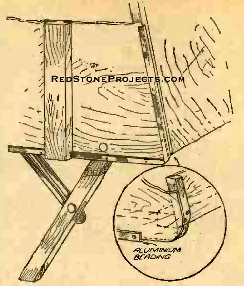
The parking jacks were then made, the design being quite
orthodox, consisting of a folding leg and adjustable stay as shown in Fig.
15. To finish off the dividing line between the green lowers and cream
uppers, strips of wood 1 in. by 3/16 in. were painted green and nailed
along the outside surface of the plywood panels. |
|
|
Figure 18. Details of one of the beds.
|
| Towing Bar
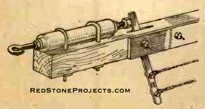
One of the last jobs was the fitting of a towing coupling
to the trailer bar. A very suitable connection was obtained from Messrs.
H. D. Trailers, Fieldgate Works, Kenilworth, for 17s. 6d., the coupling
consisting of a cylinder enclosing compression springs and a coupling rod
with a hook end for the actual connection to the car bracket. The cylinder
was secured to the tow bar by a pair of U bolts, holes for which were drilled
in the draw bar, and steel plates made and fixed underneath, thus clamping
the coupling and bar together (Fig. 19). The brake lever was fitted immediately
behind the coupling cylinder, a slot being cut in the trailer bar and a
mild steel lever 8 in. long pivoted to its center point on a bolt fitted
horizontally through the bar. The lower end of the brake lever was then
connected by cable to the brake camshaft levers in the axle unit, and cable
adjusters of the airplane type were fitted in tandem.
For maneuvering purposes, grip handles were screwed to
each corner pillar and these were found particularly useful when moving
the caravan from " dock." All is now ready for the first road test, and
it may be mentioned here that the caravan is so well balanced that in its
unloaded condition it can be balanced from the trailer bar on a fingertip,
although when travelling it is always advisable to load up the front compartment
to make it slightly nose heavy. |
|
|
Figure 19. The towing bar and automatic brake,
which is simple and effective.
|
| Final Tests
The first road test was gratifying, the braking and road
holding qualities being quite exceptional and certainly up to the standard
of various other caravans which I have previously handled. It seemed very
light and was very easily drawn by my 9-h.p. car. For anyone who knows
the district, it may be of interest to mention that the car and caravan
were taken up Peak Hill, Sidmouth, fully laden. This hill, I understand,
has in parts a gradient of 1 in 31.
Immediately following the short road test of about nine
miles, the caravan was taken on a tour round Devon, where it was eventually
parked for a few days at Sidmouth. Throughout the tour the caravan gave
no trouble whatever, and although a full kit of tools and spares were carried
there was no necessity whatever to make use of them. |
|
|
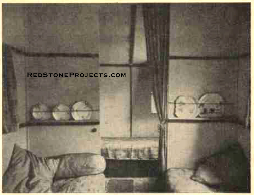
Figure 20. The inside of the" home on wheels,"
looking through the front window.
|
| Those who are skeptical about the use of plywood will
be interested to know that between September and the end of December the
caravan has been standing in an orchard exposed to all weathers and there
is no sign whatever of " lifting " or deterioration of the plywood, neither
have there been any leakages into the inside. |
|
|
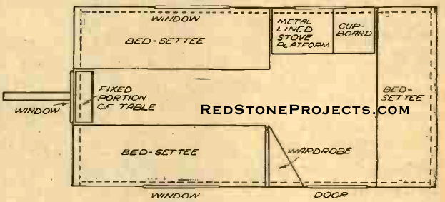
Figure 21. This plan shows the disposition of
the various fittings built into the caravan.
|
| A few words about the total cost may be of interest.
First, it should not be necessary to pay more than 30s. for an axle assembly
with springs, as most car dismantlers pay no more than £2 10s. for
a complete car. The supply of timber is best arranged from one source,
and a contract made as favorably as possible. This in particular applies
to the plywood, as it is very expensive unless purchased ix bulk. Most
of the inside fittings can be obtained from sixpenny stores, who can supply
all the window catches, cupboard hinges and locks and innumerable other
small parts of this kind. |
|
Any 2 Vintage Trailer Plans
$19.95 FREE Shipping |
|
Select 2 Vintage Travel Trailer Plans
|
|
|