 |
||||||||||||||||||||||||||||||||||||||||||||||||||||||
|
Build a 14 Foot Cabin Trailer Vintage 1940 Do It Yourself Camper Plans
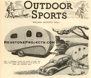
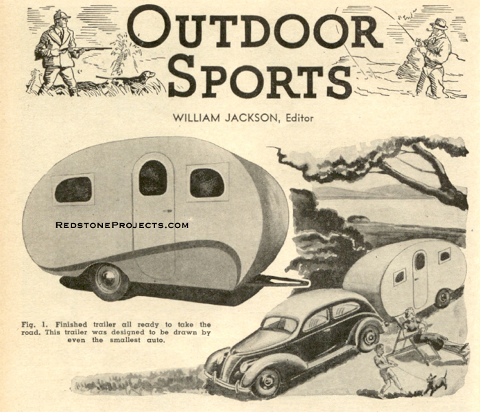
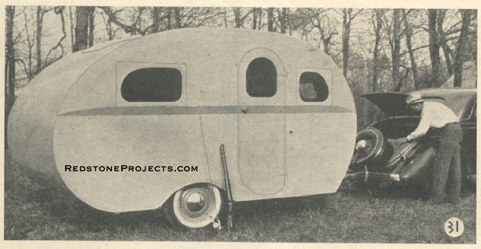
Let's Call It "TERRA CRUISER" Part I. TIME was and not so long ago when trailers were heavy and hard to handle, and they offered little comfort or convenience to their owners. The changed demands of the traveling public, however, are adequately supplied today by this easily built streamlined trailer. Adapted to construction by homecraft workers, it is comparatively inexpensive, light in weight, and due to its efficient streamlining adds an insignificant burden to any auto. It has a distinctive appearance. It provides ample space inside and is adaptable for travel anywhere, any time, with comfort, convenience and safety. In building the Terra Cruiser, SCIENCE AND MECHANICS has had the cooperation of both the Hammer Blow Tool Company and Trotwood Trailers, Inc.
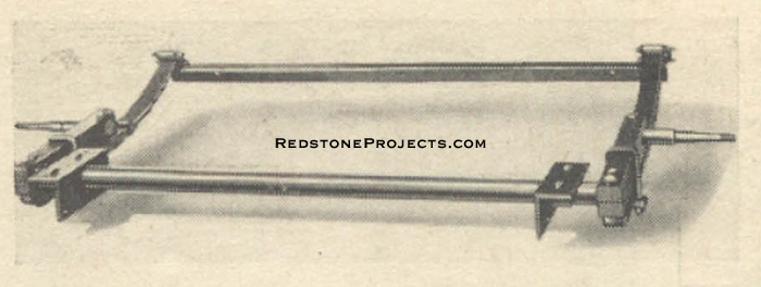
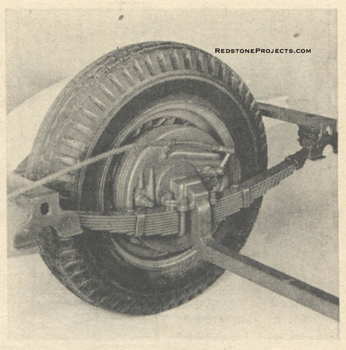
The complete under chassis (axle, springs, wheels, Warner electric brakes and controls), hitch, sink, pump, and beds were furnished to Mr. Jackson through the courtesy of Hammer Blow Tool Company. The "Step Action" axle was furnished by Trotwood Trailers so that Mr. Jackson might design the body frame to fit either unit, as well as others which might be desired. The basis of any safe and efficient trailer is the axle assembly, and this trailer is not an exception. This particular part should be selected carefully with a view towards not only easy riding qualities but the ability to track surely and evenly at all speeds.
Many cast off auto axles lack these necessary qualities, and as most standard trailer axle assemblies are sold at low prices, there is no reason to handicap one's Terra Cruiser with inefficient parts. Two representative axle assemblies are indicated on the plans. Either type is more than satisfactory, and as legislation is being expanded enforcing the use of brakes upon trailers, the axle purchased should be machined so brakes may be added at any time not only for conformity to the law but also for super safety. The axle utilized on the Terra Cruiser is of 70-inch tread width. This is wider than standard car tread, but will occasion no difficulty as all roads are now smooth, and even those not so smooth may be traveled with comparative ease with the broader, more stable tread. The trailer will pull more easily in loose sandy soil with the wider tread. To begin the construction, the material list of axle assembly parts should be scanned closely.
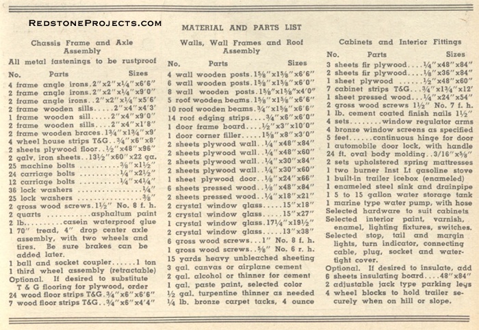
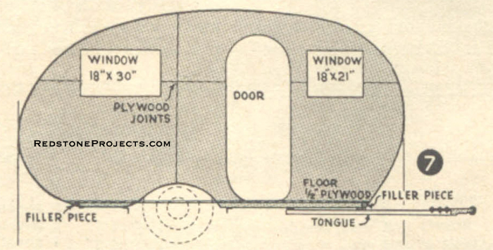
With the various parts collected, the axle assembly and wheels are set in place and the 1/4" x 2" x 2" x 9' lengthwise angle irons bolted in place to the spring hangers. The center line of the wheels is measured to square the axle assembly with the angle iron frame. These measurements are indicated upon the plans. The remainder of the axle frame assembly is quite simple and consists of squaring the angle iron crosspieces with the lengthwise pieces at the front and rear ends of wheel wells, as shown in Fig. 4, clamping the pieces together temporarily and drilling for 3/8" bolts. Square the frame parts and allow two inches clearance between each side of the tire and crosswise angle irons and bolt these 1/4" x 2" x 2" angle irons in place with 3/8" machine bolts. The ends of these angles receive and support the wheel housings later. Each end of the trailer frame is secured and reinforced with a 6' 6" length of 1/4" x 2" x 2" angle iron, installed with flange and bolted in place with 3/8" machine bolts as indicated in Fig. 4. Secure all bolts with lock washers for permanent holding. The tongue is made of two pieces of 1/4"x 2"x 2" angle iron, each 5' 6" long, bolted in place as shown with a standard ball and socket trailer coupling adapted for use with angle iron.
Your frame will be improved greatly by welding all connections where angles bolt together. However, this is not imperative if you do not have access to welding facilities. Floor and Wheel Housings The trailer frame is now ready for the attachment of wood body sills. All sills are cut from 2" x 4"'s, the center and outer sills being of fir, pine, or oak, while the sills along the spring hangers consist of a 2 x 4 ripped in the center, each half fitting inside of the trailer angle iron, as shown in the sketch at Fig. 6.
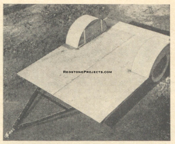
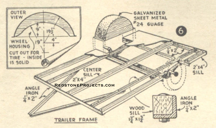
Sills in contact with angle iron should be coated with asphaltum paint before attaching, clamped in place, drilled and bolted to angle irons with 1/4" x 2 1/2" carriage bolts. The outer sills must be shimmed underneath with small pieces of thin hardwood to make all sills even and level. Nail the shims to the sills to prevent moving. A straightedge across the sills while attaching will insure a level floor. The entire frame should now be coated with two coats of asphaltum paint for utmost protection. Laying the floor is next. This floor may be either 5-ply 1/2" thickness plywood or 3/4 x 6" tongued and grooved porch flooring laid cross-wise. The original was floored with plywood, and this was laid with a seam down the center sill, while the waste cut from the sides and wheel openings was used for the rear end of the floor. Coat the underside of plywood with asphaltum paint, clamp the floor in place and fasten to the sills with 1 1/2" No. 8 f.h. screws. Let the flooring extend about three inches over the edge of the frame, both front and rear ends. The wheel openings are now enclosed as shown in Fig. 6, and if the openings vary from the plans due to other axles being used, adapt the wheel housings to the required openings. The wheel enclosures are made with 3/4" x 6" tongued and grooved flooring, making the inside of the enclosure solid and cutting out the outside for wheel removal. Strips measuring 3/4"x 1 1/2" bind the ends of the inner enclosure boards together and are fastened with screws to the floor at the opening. The outer side of the enclosure is fastened similarly. To obtain strong joints, coat the grooves of the boards with casein glue before fastening, and before securing the enclosure to the floor, coat both adjoining surfaces well with asphaltum paint. The tops of the wheel enclosures are covered with galvanized sheet iron and screw fastened in place to the edges of the enclosure sides.
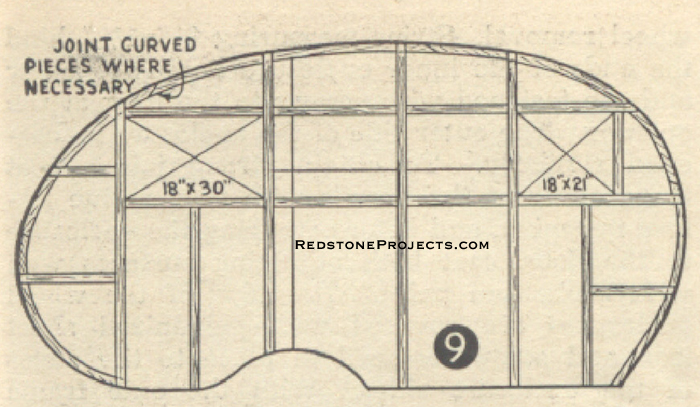
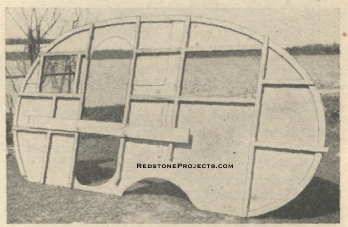
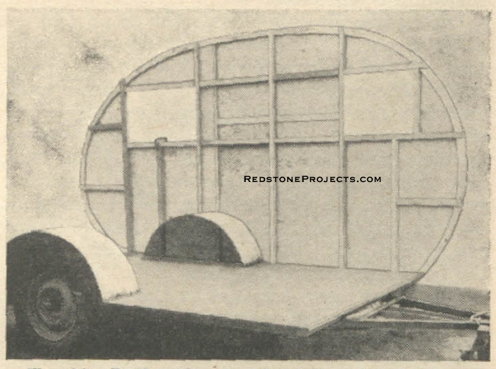
With the axle frame assembly finished, coat the floor with equal parts of linseed oil and turpentine, or if it is to be insulated later, coat it with asphaltum paint. Before further construction work is done, set up the trailer bed where it may be built without moving and block it in a level position at the four corners. Building the Walls and Side Frames Constructing the sides is next. The plans indicate details of these, and it is only necessary to lay the four sheets of plywood that comprise the sides down on a flat space, as shown in Fig. 8. Then lay out and mark the curved shape with the aid of a long thin batten sprung around so as to touch all points and saw to shape.
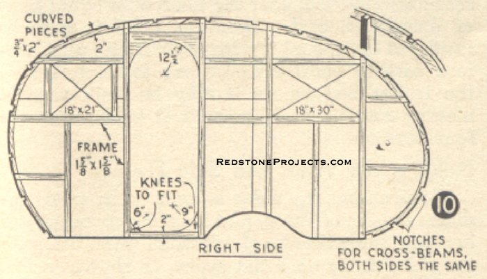
The posts at the doorway should overlap the edge of the opening 1/2" on either side, to provide a ledge for the door to close against. The pieces of plywood cut from the door and window openings are saved for constructing these parts later. A 2" x 4" should be attached temporarily across each side of the trailer to reinforce the wall until braced and fastened to the trailer floor.
Attaching the sides to the trailer platform or floor comes next. Set one wall in position so you can mark the exact position of the notches on the sills and floor. The side sills and floor are notched to receive the 1 5/8" square posts of side wall and then 1/4" x 4 1/4" carriage bolts are inserted through the trailer side and sill with the nut on the inside. Attach both sides similarly, although posts must be cut to fit at wheel housings and doorway.
At each end of the trailer floor, it will be necessary to attach filler pieces cut from 2" x 4"s so as to conform to the curvature of the sides, providing a means of attaching the roof covering at each end of the floor. Bolt the filler pieces to the frame and screw fasten to the plywood floor, trimming the floor even with filler pieces. With the two sides attached to the sills, plumb and brace the side walls together temporarily with wood crosspieces and proceed to fasten the roof beams in place. Pressed wood 1/8" x 48" x 84" is laid crosswise to cover the roof.
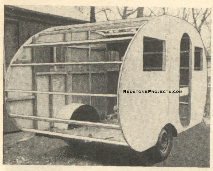
As the sheets are 48" wide, this will allow a space of three roof beams on 16" centers to each sheet. The roof beams are 3/4" x 1 5/8" fir strips with a 1 5/8" square crosspiece at each roof joint. The procedure to follow is to attach three roof beams and then a width of pressed wood, notching the crosspieces halfway into edge pieces, coating the joints with glue, and fastening with screws. The pressed wood is fastened to the roof beams and the edges of the side walls with 1" No. 8 f.h. screws spaced about three inches apart. Continue in this manner until the entire roof is covered.
Square up and brace the sides in alignment while attaching the pressed wood to in-sure square, even walls. Round the edges of the pressed wood smoothly and prepare for covering. Fill all screw holes and any irregularities with plastic wood or casein glue to which fine sawdust is added, and sand all surfaces smooth. The trailer shell is covered with heavy weight muslin cemented in place with any good grade of canvas cement. Muslin 80 inches in width is tacked in place along one edge. The surface of the plywood is coated with cement, and the cloth is pressed and smoothed onto the cement with a block. Cover the sides first, then the top, lapping the side material over the top and bringing the top material even with the sides. As the cement has considerable body by itself, the use of heavy canvas is not necessary, and heavy weight muslin is quite satisfactory.
The surface of the cloth is filled by adding alcohol to the cement and coating the entire cloth surface. When it is dry, sand smooth and apply four coats of paste paint which has been thinned with turpentine. Leave the final finishing coats until last. These should be enamel colors of preferred shades. The roof should be painted with standard exterior aluminum paint. (To be concluded in next issue)
An Easily Built Cabin Trailer
Part II COMPLETE instructions for building the under chassis, floor, walls, and roof of this cabin trailer were given in the July-August, 1940, issue of SCIENCE AND MECHANICS. Directions were also given for applying the fabric covering. The construction of the interior fittings is completed in this issue.
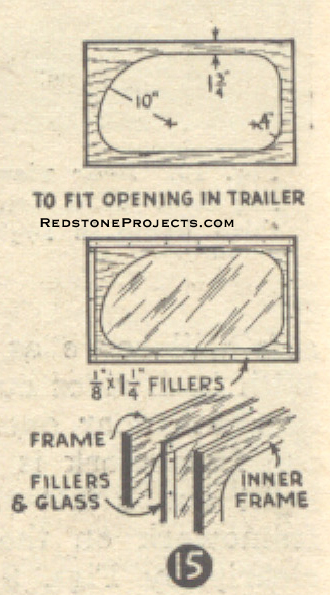
Cover the inside edges of the window openings with 1/8" x 2" strips of pressed wood. Cement the underside and screw fasten in place. The windows are made like a sandwich with the outer shell of 1/4" pressed wood, while the inner shell is the 1/4" plywood cut from the openings, as shown in Figs. 14 and 15 in the July-August issue. Cut to shape as shown, imbed glass between the shells with cement, and use 1/8" x 1 1/4" pressed wood strips for fillers to retain and position the glass between the shells.
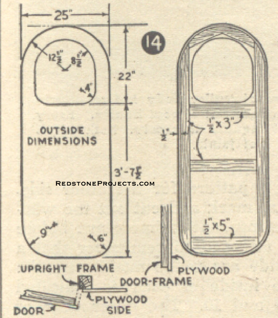
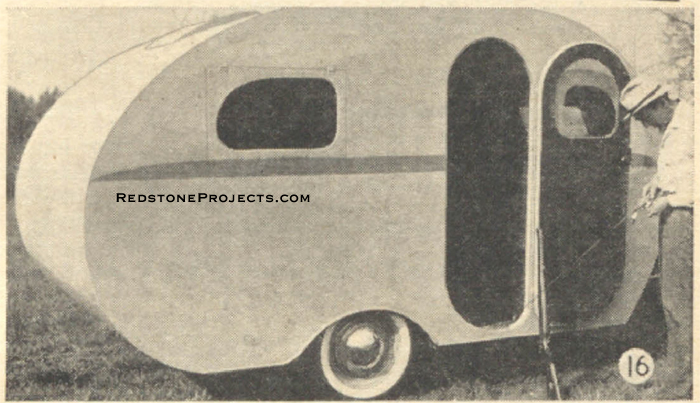
Fasten the window shells together with 5/8" No. 6 r.h. screws. Trim the windows to fit the openings. Provide a 1/2" square stop strip behind each window and attach hinges at the tops. Screens and frames are provided to fit on the inside of the window opening with a window throwout arm working through the screen frames to actuate the windows. Installing the Door The doorway is fitted with fillers, or knees, as indicated in Fig. 10 of the July-August issue, and the door itself is then fitted into place. Use separate or continuous hinges to hang door, and cover the inside edges of the door frame with 1/8" pressed wood or plywood, the same as was done with the window. Fig. 16 gives a good view of the finished door and doorway.
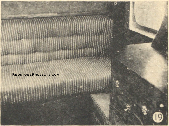
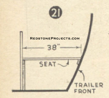
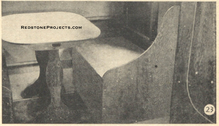
An auto type door handle is suggested for the door, although a regular key lock may be used. If desirable for through vision, cut the front and rear windows to line up with the windows of the tow car. Imbed these in cement and construct as indicated upon the plans. The interior, its fittings and arrangements allow a variety wide enough to be adaptable to any purse or purpose. The windows and outside edges may be trimmed with aluminum angle molding, and it does enhance the appearance of the exterior to trim with 3/I6" x 2" half oval aluminum molding after the painting is done. Planning the Interior The interior arrangement shown in our plan is comparatively simple and convenient and one that has been used for years with satisfaction. The large seat at the rear is furnished with two cushions of the inner spring type. One cushion serves as a backrest; the other as a comfortable lounge, as shown in Fig. 19. The drawings and illustrations here shown are full explanation of the method of construction.
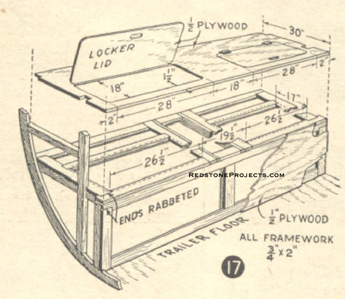
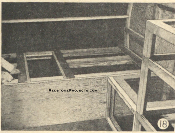
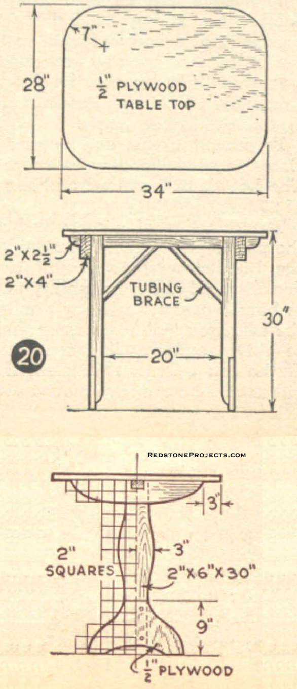
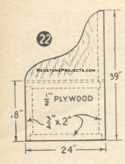
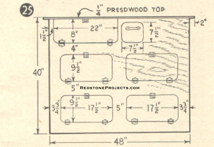
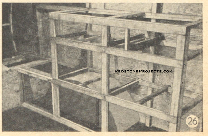
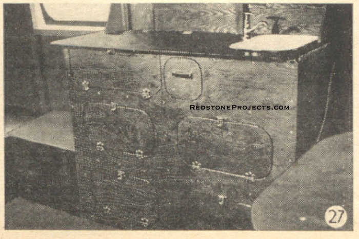
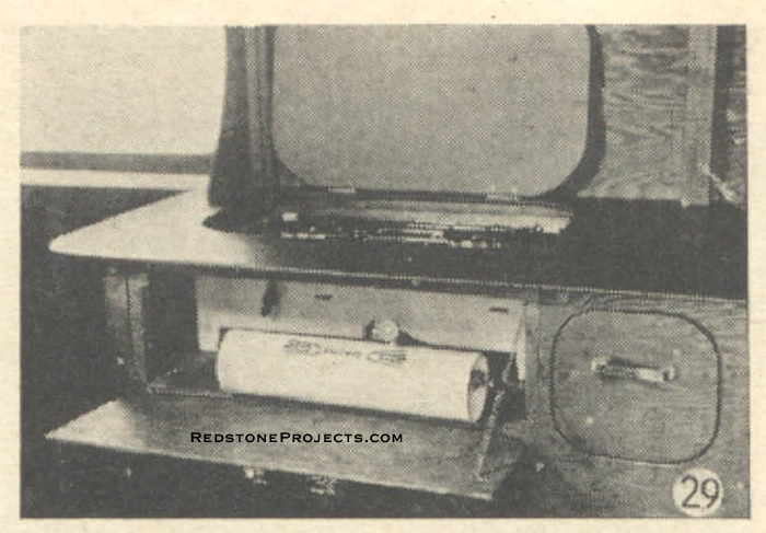
When pushed forward over the lounge seat, the two cushions form a double bed. The framework for all seats and cabinets is 3/4"x 2" strip material with one edge rabbeted as shown in detail in Figs. 17 and 24. The outer face of all cabinet work is covered with 1/4" plywood. If round corner doors and openings are cut in all cabinets, a more uniform streamlined design, in keeping with the exterior, will be effected. The breakfast nook sides and table are the only pieces constructed of 1/2" thickness plywood, and incidentally, the table may be secured to the wall with regular trailer brackets and a plywood leg or nickel-plated pipe and floor flanges. The cabinet or galley contains all culinary and food storage needs and is built as indicated. The top is covered with 1/4" pressed wood. The galley is arranged to hold the regular two-burner trailer stove with removable lids in one compartment, Fig. 29, providing a fireproof enclosure when lined with sheet metal. The sink occupies the front top half of the cabinet and is also fitted with a pump which is connected with a 5 to 15 gallon water supply tank with baffle plates and hand hole cleanouts.
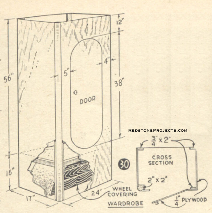
This tank should preferably be located in the rear of the trailer. For ordinary purposes a 5-gallon jug will suffice. The roof ventilator is built over the stove to ventilate and carry away odors. Additional leaves of 1/4" plywood may be attached to the end of the cabinet top for greater working table space. The icebox rests upon the floor at the front and is first lined with thick insulation material. Then a sheet metal container is inserted to hold ice and perishables. A drain is provided through the floor. Just to the rear of the doorway is the wardrobe, which is made to hold all articles of apparel, Fig. 30.
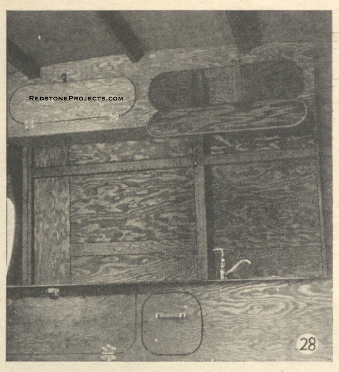
The wardrobe door is fitted with a mirror. Cup and glass racks are provided over the cabinet. Roof lockers are built in as needed, Fig. 28. Electrical wiring is carried in the walls. One dome light should be supplied and a wall fixture on each side of the breakfast nook. A light over the cabinet is a convenience.
The wiring should be for both 6-volt and 110-volt current. When parked at points whole this current is available, outlet plugs will enable the use of electric irons, toasters, etc. Stop and tail lights are fitted to the rear. Four red clearance lights are also fitted at the front and rear to outline the exact width of the trailer. Many states require two stop lights and a safety chain from the tow car to the trailer to insure safety. After all the interior cabinet work is completed, for better insulation, the inside may be celled with regular fiber wall board and all joints covered with thin wood strips. The inside should be finished in a bright color to aid vision. The cabinet work is stained or varnished in the natural finish or painted if so desired. The floor is covered with linoleum or carpet. When parked, parking legs at the corners will be of material assistance. A retractable third wheel parking leg attached to the tongue will aid in ready maneuvering of the trailer with the tow car absent. Striker plates of galvanized iron should be fitted to the lower front part of the body to reduce damage to the surface from flying stones.
|