Free Shipping
Build a Sea Craft Cabin Cruiser
Vintage 25 Foot Boat Plans and Assembly Instructions
|
Sea Craft Cabin
Cruiser Plans
Build a Vintage 25 Foot Open Cockpit Cabin Cruiser
 |
PDF Format |
|
|
All Orders Processed
On a Secure Server
|
Price $12.95
|
|
Get a restored copy of these vintage Sea Craft 25
Foot Cabin Cruiser Plans with 69 Pages of Enhanced and Enlarged
Figures and Illustrations and Searchable Text.
|
We will email these plans, to the address provided
with your payment, within 48 hours following receipt of your order.
|
|
| More Vintage
Boat Plans |
|
|

|
|
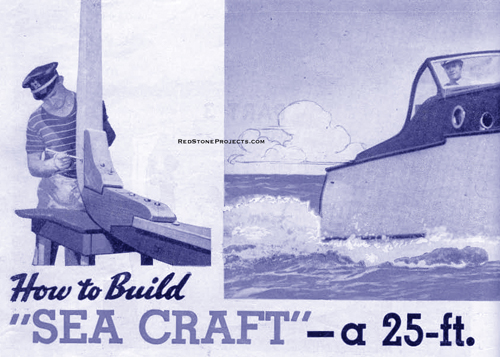
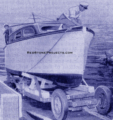
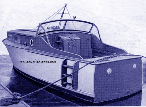
| IDEAL for use on large lakes or rivers, and fully seaworthy
for offshore ocean cruising, "Sea Craft" is a smart cabin cruiser designed
with an eye toward simple, low-cost construction for the inexperienced
boatbuilder. During World War II, the original boat was given severe tests
for seaworthiness when it was used by the United States Coast Guard to
take high ranking officers from ship to shore. The boat has an over-all
length of 24 ft., 7 5/8 in., and a breadth at sheer of 7 ft., 8 3/4 in.
A converted Chrysler "75" auto engine easily pushed it along at a cruising
speed of 15 knots. However, any marine or converted auto engine of similar
horsepower may be used.
Although this section describes the building of a sedan
cruiser, this particular hull, with a few changes in the cabin construction,
is readily adaptable to a sport fisher, express cruiser or utility boat.
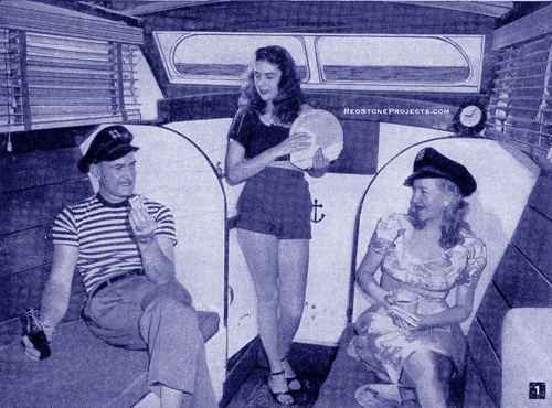
The cabin design of Sea Craft was selected because it offers one of the
best all-around accommodations. Its open cockpit is large enough for fishing,
lounging or sun bathing and the roomy cabin provides comfortable living
quarters on a long cruise. It is equipped with a fresh-water tank, sink,
cooking stove, toilet and two bunks. Two additional upper bunks can be
fitted to sleep a total of four. In addition, there is plenty of cabinet
and stowage space for gear. The photo, Fig. 1, shows the cabin interior
looking forward. |

|
|
Figure 1. Large roomy cabin with sleeping accommodations
and galley provides comfortable quarters on long cruises.
|
|
| Laying out, cutting and assembling the keel and rib structure
is by far the most important operation of building the boat. As this framework
is the backbone of the entire boat, the performance and beauty of the craft
will depend upon the accuracy and skill with which the framework is constructed.
As previously mentioned, the type of cabin, engine and even decking can
be changed to suit the individual builder's fancy, but no changes should
be made in the hull if the proven performance of this cruiser is to be
maintained.
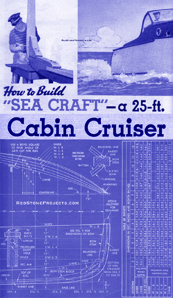
The first step in building a boat of this size is lofting,
that is, drawing the profile, the plan view and the body-plan views full-size
on paper, as shown in Fig. 4. These drawings are cut out to serve as patterns
for marking and assembling the hull frame. Full-size, cutout patterns of
the keel and ribs are available to those who care to purchase them. If
you intend to make your own patterns, get a roll of heavy wrapping paper
and edge-lap and glue enough strips together to make up the |
|
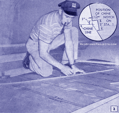
Figure 2. The full-size half pattern of each station
is drawn on heavy paper.
|
|
| required width for the height from the base line to the
top of the stem shown in the profile view, Fig. 4. The paper is tacked
down on a wooden platform - a floored attic is an excellent place - and
the profile view is drawn first, with a long straightedge or chalk line,
lay down the base line, load water line (L.W.L.) and water lines (W.L.)
from the dimensions given in Fig. 4. Then mark off the station points from
0 to 12, spacing them 24 in. apart along the base line.
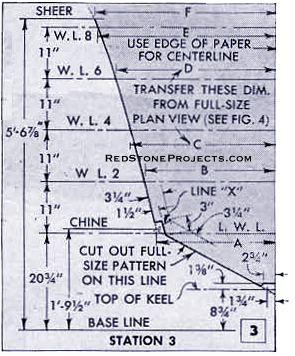
In the table of offsets at the right in Fig. 4, refer
to the column which reads "top of keel." Note that station 0 is blank because
at this point the top of keel runs into the bow stem. At station 2 the
top of keel is the bearding line. Station 3 reads 0-8-6 which means the
top of the keel is 8 3/4 in. above the base line at this point. All figures
in the table of offsets are in feet, inches and |
|
Figure 3. The natural curve of a wooden batten
is used to mark the curved line connecting half-breadth dimensions.
|
| eighth inches. For example, the 6 for station 3 indicates
6/8 in., or 3/4 in. Measure this distance from the base line along the
No.3 station line and mark it. Follow this procedure at all station lines,
marking each top-of-keel point. Drive a small nail through the paper into
the floor at each mark and bend a 3/4 x 1-in. batten against the nails.
It will be necessary to place nails on both sides of the batten at some
stations to hold it in place. The batten should be straight-grained wood
that will bend easily without any irregularity in the curve it takes. It
should be somewhat longer than the length of the boat as it will be used
later to fair the sheer, chine and water lines in the plan view. When the
batten is in position, transfer its curvature to the paper by drawing a
line along it. This is the shape of the top of the keel. The bottom of
the keel is straight. Measure 8 1/2 in. above the base line at station
0 and 1 in" above the base line 6 1/2 in. forward of station 10. Then connect
the two points with a line drawn along a straightedge or snap a chalk line.
The sharp curve at the aft end of the keel can be drawn freehand or with
a French curve. The chine and sheer lines are drawn in by the same method
used in plotting the top-of-keel line. To draw in the bow stem, knee and
bow-stem block, follow the dimensions given in Fig. 9. Use a light, flexible
batten to fair in the curves. |
|
|
Figure
4.
|
Get a restored copy of these vintage Sea Craft 25
Foot Cabin Cruiser Plans with 69 Pages of Enhanced and Enlarged
Figures and Illustrations and Searchable Text.
All Orders Processed
On a Secure Server
|
|
| Carefully mark the rabbet and bearding
lines, as these must be transferred to the bow-stem pieces after they are
assembled.
To transfer the lines to the wood,
cut the paper along the bottom of the keel and forward edge of the bow
stem. Do not cut the other lines as the pattern will he used later to lay
in the propeller-shaft angle and motor mounts. The uncut lines can be transferred
to the wood by rubbing the underside of the paper with a soft pencil and
then tracing over the lines in a manner similar to that of using carbon
paper. However, no cutting should be done until all other patterns have
been made
The keel is made of Oak, Apitong,
or straight-grained Douglas Fir, and is assembled in two pieces cut from
a single piece of timber as indicated by the dotted lines in Fig, 9. The
aft section, known as the horn timber, is spliced to the keel proper as
shown in the profile plan. Be sure to place the bolts off-center so they
will not interfere when drilling the propeller-shaft hole through the keel,
see section A-A, Fig. 4. The keel apron also should be Oak, Apitong 1 3/4
in. x 5 1/2 in., and extends from the bow-stem block to the transom. Bolt
the apron on to the keel between the stations. The dot dash lines through
the bow-stem parts in Fig, 9 indicate where to bolt them together.
A plan view, as shown in Fig. 4,
must be drawn full-size in the same manner as the profile view. First,
lay down the centerline and then draw perpendicular lines across the paper
at each station point. These station lines should be labeled clearly. Refer
to the table of offsets in the chine column of the "half-breadths from
centerline," and measure off the distance given from the centerline. |
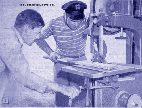
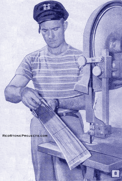
Figure 5. Angles of saw cut marked ribs
(Figure 6.) are called off by the bandsaw operator
as a helper tilts the table accordingly.
|
|
| For example, read across the chine
column under station 3, measure off the distance 2-1-2, which is 2 ft.,
1/4 in., and mark the spot. This is shown as dimension A in Fig. 4. Then
drive a small nail at the mark. Follow this same procedure at each station
for the chine, and bend the long batten against the nails. When fairing
the line, it may be found that the batten will clear some of the nails
by 1/16 or 1/8 in. This is not serious. The important thing is to have
the curve follow the natural bend of the batten. When the batten fairs
up nicely and has a smooth, flowing curve, which you can see by sighting
with your eye, draw in the line. Use the same method for all the water
lines and the sheer line until you have a full-size drawing of the plan
view as in Fig. 4. To avoid confusion later, draw each line a different
color.
Full-size drawings of the body-plan
sections, Fig. 4, become patterns for marking the ribs and assembling the
frames. Cut a piece of paper for each station. The paper must be perfectly
straight along one of the long sides which is used as a centerline. Draw
a base line at right angles to the centerline, 2 in. from the bottom edge.
Taking station 3 as an example, draw in the load |
|
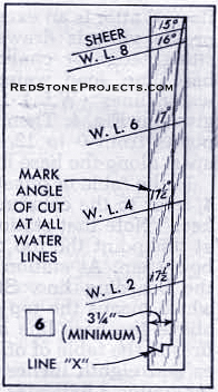
Figure 6. Angles of the saw cut are marked on
ribs.
|
|
water line and water lines 2, 4, 6 and 8 parallel with the
base line from the dimensions given in Fig. 3. These lines are spaced the
same for all stations. Identify each line.
The table of offsets is not used to draw in the lines
for the rib patterns. All dimensions are taken from the faired lines of
the full-size plan and profile drawings. On the profile drawing, measure
up from the base line for the top-of-keel, chine and sheer lines at station
3 and transfer them to the station-3 rib pattern. From these points, draw
lines parallel with the base line and identify each. On the plan view,
measure the distance from the centerline to the chine (see dimension A,
Fig. 4) and mark this distance on the chine line of the patten by measuring
in from the edge of the paper used as a centerline. Follow the same procedure
in transferring dimensions B, C, D, E and F, Fig. 4, to their corresponding
lines on the rib patten. Drive a nail at each point marked, fair a batten
against the nails, and scribe the line as in Fig. 2. Using a straightedge,
scribe a line from the point marked on the chine line to a point 1 3/4
in. from the edge of the paper on the top-of-keel line. Dimensions for
the notch over the keel apron and limber holes, indicated in Fig, 10, are
given in Fig, 3 above the top-of-keel line. These dimensions apply to all
stations except stations 1 and 2, which are slightly
|
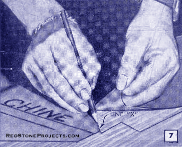
Figure 7. Marking the ends of the ribs.
|
|
| narrower because the apron tapers to 3 1/2 in. where
it joins the bow-stem block.
To draw in the notch for the chine batten, draw a line
parallel with and 1 1/2 in. from the faired line at the chine end. Measure
3 in. along this line from where it intersects the straight line from the
chine to top-of-keel. All chine notches are made the same way with the
exception of station 1, shown in the inset of Fig, 2, Line X, Fig, 3, indicates
where the two ribs join and is located by scribing a line from the point
of intersection of the straight and faired lines to the point of intersection
of two lines drawn parallel with and 3 1/4 in. from the straight and faired
lines. Cut out the pattern as indicated by the shaded area in Fig, 3, allowing
it to extend about an inch beyond the sheer line for trim. Also, make a
cut on line X to mark the ends of the ribs as shown in Fig. 7, All rib
patterns are drawn and cut out as previously described, except station
12 for which the following method is used: On the full-size plan view strike
a 12-ft. arc extending across the chine, sheer and water lines with a string
centered at station 6. To determine the half-breadth dimensions for station
12, or the transom, measure the distance from the centerline to where the
arc crosses the water lines. |
|
Figure 8. A compass or marking gauge set at 3
¼ in. is used to scribe a line conforming to the contour of the
outside edge of rib. This becomes the inside edge of the rib.
|
|
| Use Oak, Apitong or vertical-grained Douglas Fir, l in.
thick, for rib stock. Each frame, with the exception of station 1, has
four ribs held together with gussets and tie bars as shown in Fig. 10.
Station 1, being narrower, requires only one rib on each side. Mark the
rib stock by laying the full-size pattern directly over the wood and scribing
a pencil line along the edge of the pattern, Fig, 7. Allow at l east 3
1/4 in. for the width of the rib. After marking the sheer, chine and all
water lines on the rib stock, refer to the full-size plan view and measure
the angles at the sheer and waler lines with a bevel square as indicated
at station 4, Fig, 4. Then, mark these angles at their respective water
lines |
|
Figure
9.
|
Get a restored copy of these vintage Sea Craft 25
Foot Cabin Cruiser Plans with 69 Pages of Enhanced and Enlarged
Figures and Illustrations and Searchable Text.
All Orders Processed
On a Secure Server
|
|
| as shown in Fig, 6. When making the angle cut on a bandsaw,
it is a good idea to have a helper, as in Fig. 5, because he can change
the angle of the cut as marked at the various water lines while you guide
the board. |
|
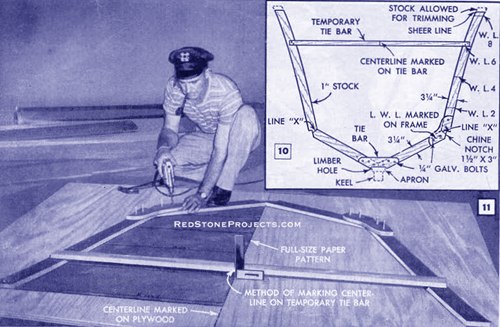
Figures 10 and 11. Ribs, gussets and tie bars
are assembled directly over full-size patterns to assure exact alignment.
Builder is shown drilling bolt holes through gussets and ribs. Note how
centerline is marked on temporary tie bar.
|
|
| Cut two sets of ribs for each frame, but be sure to reverse
the angle cut so that the ribs can be assembled as pairs. If a tilting-table
bandsaw is not available, you can cut the angle with a wood chisel or block
plane after the rib is sawed. However, this method is much slower and not
quite as accurate, Mark the line for the second cut of the rib with a compass
or marking gauge set at 3 1/4 in., as in Fig. 8. Leave the penciled water-line
marks on the ribs as they are, but cut a small notch at the load water
line so that it can be located after the frame has been painted.
Assemble the frames either on a wooden floor or on two
sheets of plywood fastened together. Draw a heavy line on the floor to
serve as a centerline and line up the edge of the full-size pattern with
it. Then place a bottom and side rib directly over the pattern to assure
perfect alignment and temporarily nail a gusset to the ribs to hold them
together. Pencil marks made on the floor along the outside edge of the
ribs will help locate their position when the paper pattern is slid out
and turned over to assemble the ribs for the other side of the frame. When
both sides are assembled, carefully check the distances from centerline
to sheer on each side and nail the temporary tie bar across at water line
6, as shown in Fig. 10. Then bolt the tie bar across the bottom with its
lower edge flush with the notch for the keel apron. The tie bar is 4 in.
wide and is made of the same material as the ribs. The gussets are also
1 in. thick and extend about 8 in. each way from the chine corner. Their
curves may be drawn freehand.
The gussets are then bolted to the ribs. Before removing
the frame from the floor, carefully mark the centerline on the temporary
tie bar using a square edge as indicated in Fig. 11.
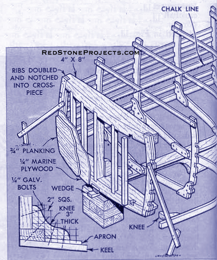
Blocking the Keel
When the keel, apron and bow-stem parts have been bolted
together, a suitable erection site must be selected. As a boat of this
size, in most cases, requires being built outdoors on uneven ground, blocking
is necessary to support the bottom of the keel at the correct angle in
relation to the base line. A leveled chalk line stretched between two stakes
to correspond to the base line of the profile drawing, will serve as a
starting point from which to measure heights of the blocks. The exact heights
can be determined by taking measurements from the base line to the bottom
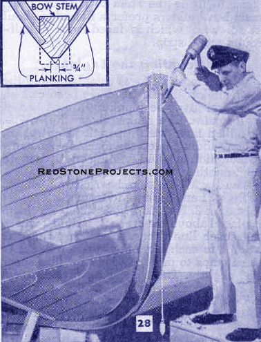
of the keel on the full-size profile drawing. Two wedges driven between
the keel and a block, Fig. 19, make a close adjustment possible. The bow
stem also must be lined up perpendicular athwartships. This can be done
with a plumb line fastened to the top of the bow stem, as in Fig. 28.
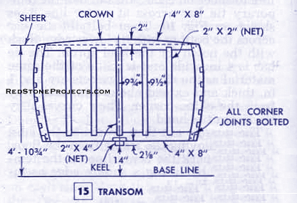
The transom is made as shown in Figs. 15 and 16. The aft
edges of the top and bottom timbers have a convex curve of 12-ft. radius
as in the plan view shown previously. The top timber is crowned 2 in. and
the bottom timber is notched for the apron, and tapered 1/8 in. from keel
to chine on the lower surface. When assembled, the transom is bolted to
the keel with a knee block, as indicated in the lower left-hand detail
of Fig. 16. It must be perpendicular to the base line and exactly centered
on the keel.
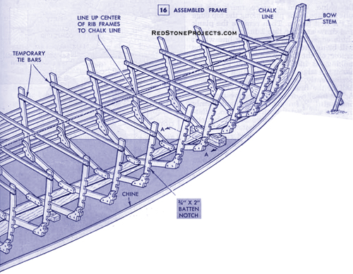
Before assembling the rib frames on the keel, refer to
the profile view, Fig. 4. Note that the No.6 frame straddles the station
line and that frames 1 to 5 inclusive arc forward of the station lines,
whereas frames, 7 to 12 inclusive are aft of the station lines. This refers
only to the thickness of the rib and does not apply to the thickness of
the tie bar. To start assembling, first mark each station line on the apron.
Then draw a second line representing the thickness of the rib and set up
the frames between the two lines. |
| Use galvanized lag bolts to fasten the frames to the
apron, Fig. 17. A chalk line from the center of the keel to the center
of the transom, Fig. 16, is used to line up the frames with the centerlines
marked on the temporary tie bars on each frame. The frames also must be
at right angles to the keel athwartships and should be well braced.
The chine, which is vertical-grained oak, is fitted to
the frames in one piece from bow to stern. To determine the position on
the bow stem where the chine notch should be cut, clamp the chine in the
rib notches and bend it over to the bow stem. The chine notch on the other
side of the bow stem should be exactly opposite this point. Before fastening
them permanently, be sure none of the station frames has been sprung out
of position, A board clamped across the tie bars as in Figs, 13 and 14
will help keep the frames aligned. |

|
| Screw the chines to the bow stem and transom with 1 1/2-in,
No. 9 galvanized screws and bolt them to each rib gusset as in Fig, 17.
Sea Craft is planked with 3/4-in. Philippine mahogany, but other woods,
such as White Cedar or vertical-grained Douglas Fir may be used. Be sure
that all lumber is boat stock and keep in mind that it must be wider than
the final width of the planks. In some cases, a 10-in. piece will make
only a 6-in. plank. There is no set width for the finished planking. However,
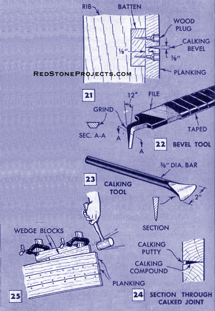
planking of uniform widths will give the best appearance. The battens are
3/4 x 2-in. and of the same material as the planking. They are notched
into the ribs and may be spliced over a rib. When laying out the batten
notches, measure upward from the bottom of the chine so that the center-to-center
distance between the battens will equal the width of the planks. In this
way, the seams between the planks will be directly over the centers of
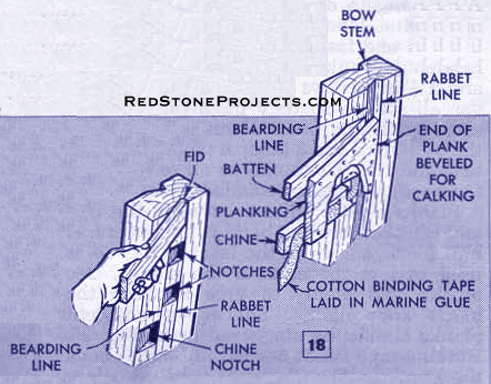
the battens as in Fig. 21. The battens are notched into the bow stem the
same as the chines so the planking will fit snugly into a rabbet cut in
the bow stem, Fig. 18. Notches are cut at intervals between the rabbet
and bearding lines and checked for correct depth and angle with a fid,
which is a small block the same thickness as the planking, Fig. 18. Then
the waste is removed between these notches to form a continuous rabbet.
When installing the battens alternate them from port to starboard side
to equalize the strain on the frames.
As the side planks lap over the transom planking, the
transom must be planked first. Cover the transom frame with 1/4-in. marine
plywood and fasten with flat-headed screws, countersunk. Then screw 3/4-in.
mahogany planking over the plywood, counterboring the screw holes to take
wooden plugs as in Fig. 21. For a neat appearance, run the grain of the
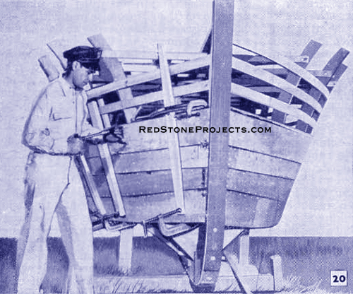
plugs the same way as the grain of the planking. When planking the sides,
start at the chine and alternate from side to side, being sure that the
plank ends fit correctly into the bow-stem rabbet. Clamp the plank in place
at the bow stem and mark for cutting. Then remove, cut and reclamp for
further fitting. Repeat until you have a good joint. It will be necessary
to steam the forward ends of all planks to prevent breakage. To avoid marring
the wood when clamping the planks, use a strip of wood between the clamp
and plank as in Figs. 12 and 20. Work from the bow toward the stern, keeping
the bottom edge of the plank even with the bottom edge of the chine. When
in place, mark the inside surface of the plank along the top edge of the
first batten. Then remove the plank and draw another line 1 in. in toward
the chine edge. This is the cutting line which will bring the edge of the
plank over the center of the batten. A slight bevel for calking. as in
Fig. 21, should be planed along the edge. Before attaching the plank permanently,
coat the chine and lower half of the first batten with marine glue. Apply
muslin, or cotton binding tape and more glue. Then clamp the plank firmly
in place and fasten with 1 1/4-in. No.8 flatheaded galvanized screws at
the battens and 1 1/2-in. screws at the bow stem. Stagger all screws so
they do not run in the same grain and place about 1 in. apart at the bow
stem and 3 in. apart along the battens and ribs. Counterbore all screw
holes for wooden plugs to be added later.
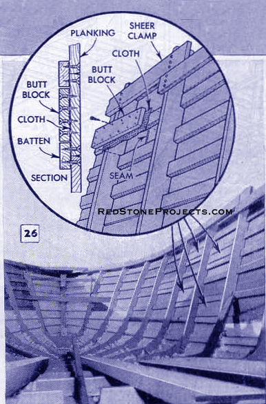
Planks can be spliced between the ribs amidships where
the bend is not severe. A butt block, shown in the inset of Fig. 26, is
used to join the ends of the planks. Use muslin and plenty of glue between
the block and planks. Splices in adjacent planks should be staggered as
in Fig. 26.
Binding tape is not needed in seams above the L. W. L.
Fig. 25 shows how the edges of the planks are drawn tightly together with
wedge blocks.
Turn the boat over after all the side planks, except the
sheer plank, are in place. This is left off to prevent it from being damaged.
The bow-stem rabbet must be continued along the entire length of the keel,
and the apron must be beveled flush with the bottom edge of the ribs. At
this time, be sure the notches that serve as limber holes have been cut
in the ribs on each side of the apron, |
|
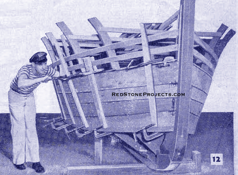
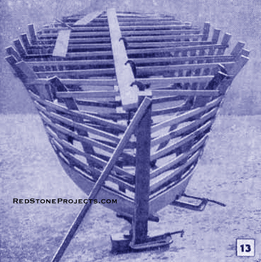
Figure 13. A plank, extending the full length
of the boat and clamped to temporary tie bars, will help keep the frames
in proper alignment when installing the battens and planks.
|
|
| Fig. 17. Also be sure the stopwaters
are in place. These are 1/2-in. softwood dowels dipped in paint and driven
into holes drilled through the keel athwartships between the rabbet and
bearding lines at four places as in Figs. 4 and 9.
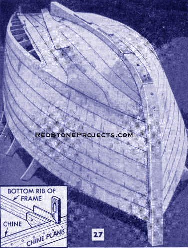
The bottom edge of the chine and
chine plank must be planed flush with the bottoms of the ribs. Test with
a small square as detailed in Fig, 27. The bottom planks, especially forward,
require considerable fitting and cutting to bring them to exact shape.
A cardboard template for the forward end of each plank will simplify
this fitting job. Fig. 27 shows the unusual |
|
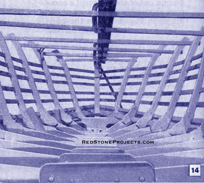
Figure 14. Interior of the assembled frames looking
forward.
|
|
| contours the bottom planks assume at the forward end.
It is best to install the bottom battens as the planking proceeds. Binding
tape laid in marine glue is used on all bottom planks, Install the planks
adjacent to the keel first, and then work toward the chine.
When this much of the planking is completed, wooden plugs
dipped in marine glue are driven into the counterbored screw holes and
cut off flush with the surface. The plugs can be purchased and should be
of the same material as the planking. The bottom of the keel is planed
flat to approximately the position of the second station. From this point
forward the keel takes a slight bevel, which tapers to a sharp bevel at
the bow stem, shown in Fig. 28. |
| Sand, calk and paint the bottom before turning the hull
upright. Although a power belt sander is preferred, a disk sander may be
used if care is taken not to gouge the planking. To clean out the plank
joints for calking, bend and grind the tang of a file as shown in Fig.
22. Cotton marine calking is driven into the seams with the calking tool
shown in Fig. 23. Use plenty of caulking along the keel seams. However,
one strip between planks is usually enough because room must be left for
the calking putty, which is applied with a knife over the calking cotton.
The putty is slightly indented below the surface as in Fig. 24. To prevent
the bottom from drying out, give it a coat of copper bottom paint. The
hull is quite heavy now so probably you will need more help to turn it
over. As the boat will remain in this position until it is finished, level
the
L.W.L. and securely block the hull in position. |
|
Figure 16. Assembled Frame (Aft View)
|
|
|
Figure 16. Assembled Frame (Forward View)
|
|
| Next, install the top or sheer planks. Carefully fit
the bottom edge of the planks and clamp in position on the hull. Transfer
the sheer-line marks on the ribs to the sheer planks and cut them slightly
oversize at the sheer lines to allow for planing later. When the sheer
planking is in place, plug the screw holes and calk the seams. Then sand
the transom smooth, fill with a mahogany-colored wood filler and follow
with two coats of marine varnish. The inside of the hull is painted with
a mixture of white lead and linseed oil. |
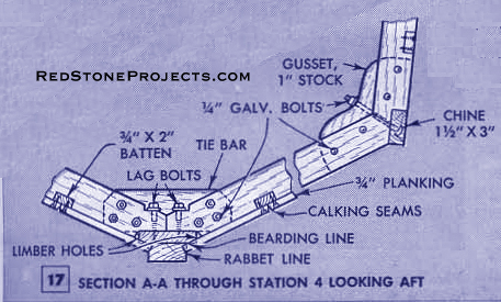
|
Figure 17. Section A-A Through Station 4 Looking
Aft
|
|
| The best way to bevel the edge of the bow stem is with
a wide wood chisel as shown in Fig. 28. Although there is enough stock
to bring the stem to a sharp edge, most boatbuilders prefer a flat edge
about 3/4 in. wide which is faced with a half round metal strip. |
| Mounting the Engine
When the planking is completed and the seams below the
L.W.L. have been calked, sand and give the planking a coat of flat white
paint. The seams above the L.W.L. are filled later with a plastic scam
sealer. When sanding, keep the machine constantly in motion to avoid sanding
one area more than another, thus causing low spots. |

|
Figure 19. Method of Blocking Under Keel
|
|
| The 1 x 3 1/2-in. oak sheer clamps, shown in Figs. 31
and 38, extend from the transom to station 2. Note in Fig. 30 that one
clamp is placed above the other at station 7 where the sheer line drop.
When screwing the clamps to each rib, allow the top edges of the clamps
to project above the hull sheer line slightly. These are later planed down
to come flush with a 2-in. crown in the decks. The sheer clamps from station
1 to the bow stem are lapped and bolted to the long sheer clamps at station
1 and are fastened to the bow stem with a block.
At this time, decide what kind of an engine will be used
in the boat. A marine engine is best. However, many automobile engines
work well when converted to marine use. Kits are available for converting
the engine yourself, or a marine machinist can convert your engine by removing
all gears except the reverse and high gears and installing a thrust bearing.
A water pump to circulate cooling water also is necessary. Sea Craft's
Chrysler engine, Fig. 29, was converted in this way, Note the extra oil
sump welded to the bottom of the oil pan to permit the engine to operate
on an angle.
The engine-bed pieces, Fig, 33, are made of 2-in. oak
and bolted to the engine stringers. Fig. 38, which extend from the transom
to a 2 x 4-in. tie bar, which replaces the original tie bar on the frame
of station 6. The engine stringers are placed approximately parallel with
the keel apron, and are notched out and screwed to the lower transom beam
and ribs. If placed 19 in. apart they will accommodate most engines. However,
this dimension should be checked with the engine before installing them.
The floor stringers, Figs. 33 and 38, are bolted to the outside of the
engine stringers and are notched for the ribs to which they are screwed. |
|
| The port stringer extends from station 3 to 5/8 in. forward
of station 8; starboard stringer from station 3 to 11 5/8 in. aft of station
8. |
|
Figures 21, 22 ,23, 24 and 25. Caulking bevel,
Bevel tool, Caulking Tool, Section through caulked joint, and Wedge blocks
respectively.
|
|
| Before determining the shape of engine bed pieces and
the location of the propeller shaft hole, the exact position of the engine
in the hull must be determined. This can be done best by making a full-size,
cutout pattern of the engine profile on heavy paper. Carefully mark the
location of the mounting brackets and center line of the crankshaft on
the paper. Place the pattern on the full-size profile drawing between stations
6 and 8 and shift it around until the crankshaft center line is at an angle
of 10 deg. or less with the L.W.L. Check the oil pan, flywheel and the
transmission housing for clearance with the apron and ribs. When the engine
pattern is in position, Fig. 30, fasten it down with tape and draw an extension
of the crankshaft line across the keel and apron. |
|
Figure 26. Planks are butted together between
ribs and joined with a butt block. Adjacent splices are staggered.
|
|
| Other parts, such as the rudder, propeller, shaft log,
rudder post and propeller shaft strut, shown in Figs. 30 and 33, should
be on hand so they may be sketched in on the profile drawing to check for
clearance. |
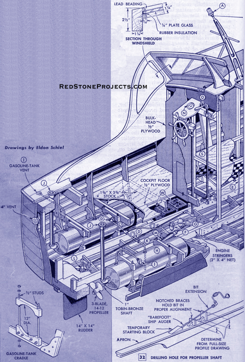
| A method of holding the bit at the correct angle when
drilling the propeller shaft hole is shown in Fig. 32. The braces and starting
block should be sketched on the profile drawing and their exact location
transferred to the hull. Since the propeller shaft is 1-in. diameter Tobin
bronze, the hole must be 1 1/4 in. It is started with a regular wood bit
because a "barefoot" ship auger has no lead screw. In the event the hole
runs out slightly, a bar of iron heated red-hot can be used to burn the
hole in the proper direction. |
| Next, bolt the propeller shaft strut to the keel, and
drill a hole through the transom knee, apron and keel to take the rudder
port. Locate the positions of the strut and port from the sketches made
on the profile drawing. Assemble the shaft log to the apron temporarily
with two wood screws and insert the propeller shaft. |
| A flanged coupling is used to connect the shaft to the
engine. The engine stub shaft and the propeller shaft will require some
machining to take the flanged coupling. After setting the engine on its
bed, it can be lined up with the shaft by bringing the faces of the coupling
flanges together and gauging the distance between them at four places 90
deg. apart around their periphery with a mechanic's feeler gauge. The shaft
log may have to be shifted somewhat and the engine raised or lowered to
get them in proper alignment. If the installation makes it impossible to
line up the engine and shaft, a universal joint and thrust bearing can
be installed between the coupling and shaft log. After the boat has been
in the water a while, the propeller shaft may start to "pound" due to dampness
from the bilge swelling the engine bed and throwing the motor out of alignment.
However, once the motor has been realigned it rarely requires further adjustment. |
|
Figure
30.
|
Get a restored copy of these vintage Sea Craft 25
Foot Cabin Cruiser Plans with 69 Pages of Enhanced and Enlarged
Figures and Illustrations and Searchable Text.
All Orders Processed
On a Secure Server
|
|
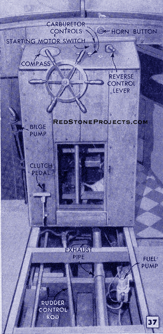
| Although many boats do not have a clutch-control pedal,
it will be found useful. If an automobile engine is used, it is a simple
task to saw off the clutch pedal, install the necessary linkage and connect
to a foot pedal extending out of the control box, Fig. 37. The gearshift
lever also is sawed off and connected to the forward and reverse lever
as in Figs. 30 and 38. |

|
| Water to cool the engine is piped from an intake scoop
to the pump. The scoop is fitted in a hole drilled in the bottom of the
hull Engine exhaust gases are carried through a 2 1/2-in. galvanized pipe
from the engine manifold to a hole in the transom 2 in. above the L.W.L.
Cooling water from the engine also runs out the exhaust pipe. Asbestos
must be wrapped around the exhaust pipe between the manifold and the cooling-water-pipe
connection. The water keeps the rest of the exhaust pipe cool.
Sea Craft has two 24-gal round tanks supported by cradles.
However, any type of marine gasoline tanks can be used provided they have
the fill pipe connected to deck plates located on an open deck so there
is no danger of gasoline being spilled into the bilge. The tanks also must
be vented through the hull as indicated. Copper tubing, coiled to absorb
vibration, carries the gasoline to the engine by means of an electric pump.
The tank outlet is the type fitted to the top of the tank to minimize the
possibility of leakage.
Air for engine and bilge ventilation is supplied by sheet-metal
ducts between stations 6 and 7, Figs. 30 and 35. Circulation is maintained
by two plate vents in the transom. |
| Cabin Construction
The size of the cabin and the arrangement of the bunks,
cabinets and bulkheads is a matter of personal choice and may be changed
without affecting the performance of the boat. If more headroom is required,
the cabin sides can be made higher or, if less headroom is desired, the
cabin floor may be raised slightly. Also, the length of the cabin can be
shortened to provide a |
|
Figure 32. Drilling Hole for Propeller Shaft
|
|
| larger open cockpit. However, regardless of the changes
made, the methods of construction shown in the drawings should be followed.
All structural members must be fastened to the frames, never directly to
the hull planking. Stock size fir or spruce can be used for most of the
framing and the plywood must be of the type made especially for marine
use. |
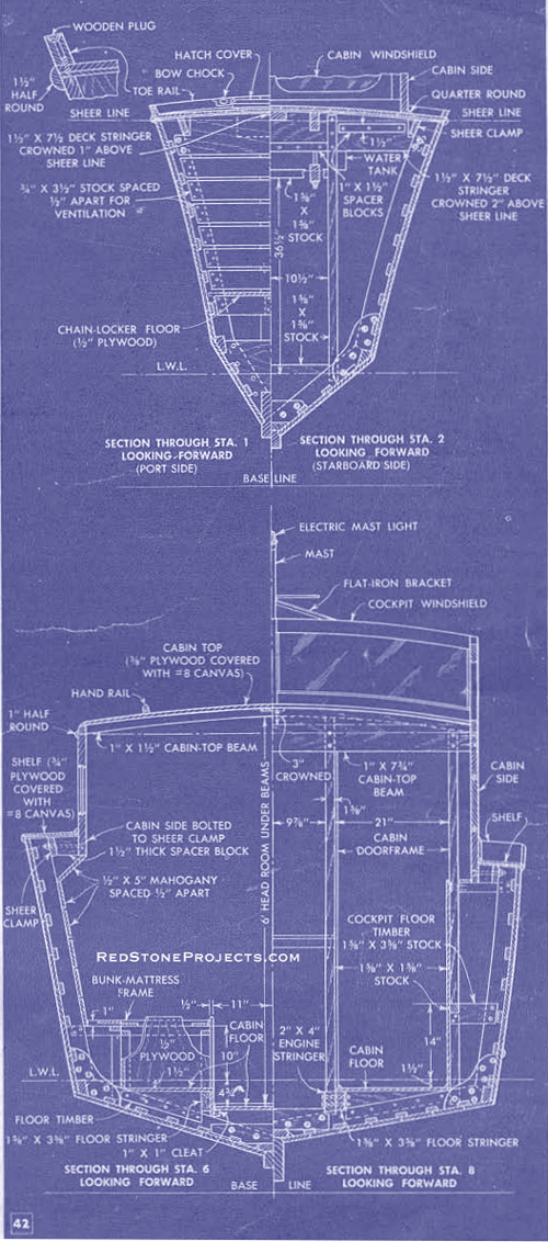
| Sea Craft's forward deck extends from the bow to station
2. Two deck stringers, shown in the upper drawing of Fig, 42, are bolted
to the aft and forward sides of the frames at stations 1 and 2 as shown
in Fig. 38. The top edges of the stringers are notched for the cradle of
the fresh-water tank and a 1 1/2 x 6-in. center beam, which is bolted to
the stringers as shown in Figs. 30 and 38. The shape of the cradle, which
is made of 1 1/2 x 3-in. oak, must be determined by the tank dimensions.
Refer to the perspective drawing, Fig. 33, for clarification. The frame
for the hatchway opening, indicated in Fig. 38, projects 2 in. above the
stringer. This opening gives access to the chain locker, which is floored
and partitioned as shown in Figs. 30 and 42. |
| Cleats of 1 x 1-in. stock, screwed to the sides of the
hatchway frame flush with the top edge of the stringer, support the l/4-in.
plywood, which is screwed down to cover the entire deck area. After the
plywood has been covered with marine glue and canvas, it is planked with
1/2 x 3-in, mahogany. The white lines between the planks are made by beveling
the planks slightly, as for calking, and then filling the resulting grooves
with sealing compound, Although the 3-in. planking can be laid to the sheer
line, a margin plank on each side, as in Fig. 40, will improve the appearance.
Details of the bulkhead at station 2 are given in Figs. 41, 42 and 43. |
| The cockpit floor is supported by timbers which extend
athwartships and bolt to the forward sides of frames 9, 10 and 11 and the
aft side of frame 8. A portion of the cockpit floor timber at station 8
is sawed out later for the stair well to the cabin. Note in Fig. 40 that
the center section of the floor is removable and that it rests on two strips
of 1 5/8 x 1 5/8-in. stock which are notched into the athwartship floor
timbers. The outboard edges of the strips are located directly above the
engine stringers. These pieces extend from station 8 to the vertical transom
braces. Fig. 37 shows this section of floor removed. |
|
Figure
38.
|
Get a restored copy of these vintage Sea Craft 25
Foot Cabin Cruiser Plans with 69 Pages of Enhanced and Enlarged
Figures and Illustrations and Searchable Text.
All Orders Processed
On a Secure Server
|
|
| The stern-deck stringer, which is crowned 2 in., the
same as the top transom timber, is placed 16 in. forward of the transom
and lag-bolted to a 3-in. knee block fastened to the sheer clamp and transom
timber as indicated in Figs. 40 and 41. |
| The cabin sides are installed next. First make the 1
1/2-in. thick spacer blocks shown in Fig. 40. Considerable fitting will
be required when installing the blocks. The inboard edges of the blocks
must be perpendicular to the base line and their top edges must be on a
slight downward angle to the sheer line to coincide with the 2-in. crown
of the decks, when fitted, toenail them to the sheer clamp. Note that the
dimensions for the blocks at stations 3, 4 and 5 have been omitted. These
are installed after the cabin sides are clamped in position.
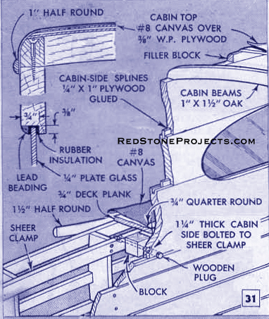
Each cabin side is made up of three pieces of 1 1/4-in.
(1 3/16 in. net) mahogany, splined and glued as indicated in Fig. 31. The
total width of the glued-up boards should be not less than 28 in. If three
9 1/2-in. boards are used, each side will require two pieces 20 ft. long
and one piece 16 ft. long. However, if the headroom is to be increased,
the width of the cabin sideboards must also be increased. To layout the
shape of the sides, joint the seam edges of the boards and lay them together
on a flat surface. As the lower' corners of the cabin sides are notched
to fit 3 1/2 in. below the sheer line between the bulkhead at station 2
and the stern-deck stringer, the developed length must be obtained. This
can be done best by fairing the batten against blocks and cutting it off
to fit between the bulkhead and the stringer. |
|
Figures
40 and 41.
|
Get a restored copy of these vintage Sea Craft 25
Foot Cabin Cruiser Plans with 69 Pages of Enhanced and Enlarged
Figures and Illustrations and Searchable Text.
All Orders Processed
On a Secure Server
|
|
| With the batten in place, mark the position of each station
on it, then remove, place on the cabin sideboards and transfer the station
locations to the sideboards. Draw lines across the boards perpendicular
to the seams at the station marks and ends of the batten. Note in Fig.
40, section G-G, that the cabin side projects over the forward deck 5 1/2-in.
A chalk line parallel with and 64 1/4-in. above the L.W.L. is stretched
between two temporary upright braces at station 2 and the transom to represent
the top of the cabin sides. The distance between the chalk line and the
bottom of the sheer clamp or blocks at each station is measured and transferred
to the cabin sideboards. A line connecting these points gives the bottom
cutting line of the cabin side. The line between stations 6 and 7 drops
abruptly because of the sheer drop. The curved lines of the cockpit sides
and cutouts for the windows are drawn freehand with the aid of a pattern
of squared lines drawn lightly on the boards as in Figs. 30 and 41. |
|
Figure
43.
|
Get a restored copy of these vintage Sea Craft 25
Foot Cabin Cruiser Plans with 69 Pages of Enhanced and Enlarged
Figures and Illustrations and Searchable Text.
All Orders Processed
On a Secure Server
|
|
| The aft ends of the cabin sides project about 1 5/8 in.
over the stern deck. When cutting the spline grooves, stop them so they
will not run out in the end grain of the windows and the curve of the cockpit
sides. The forward edge can run out as it is covered by the windshield
frame. When assembling the boards, use marine glue and clamp securely until
dry. Then layout the port-light hole and the forward end which slopes about
36 deg. off the vertical. After sawing, rabbet the edges of the window
openings, as shown in Fig. 31, to take the plate-glass windows, which are
installed later. As both cabin sides are the same, the completed one can
be used as apattern to layout the second side. Care should be taken to
make the rabbeted edge around the window openings on the outside of each
piece.
When installing the cabin sides, nail temporary tie bars
across frames 5, 6 and 7 just below the sheer clamps, and use timbers and
wedges or automobile jacks at stations 6 and 7 to force the cabin sides
against the spacer blocks. Before making the spacer blocks for stations
3, 4 and 5, wedge and clamp the cabin sides until they are fairly straight
between stations 2 and 5 so the window glass will seat tight against the
rabbeted edges. When the sides are clamped firmly in position, bolt them
to the sheer clamps at each spacer block with large headed, 3/8-in. galvanized
carriage bolts. Countersink all bolts and plug the holes for neat appearance.
Before removing the clamps, install the cabin top beams
shown in Figs. 35 and 40. The forward beam is placed 7 1/4-in. aft of the
forward top corners of the cabin sides. The other frames are spaced uniformly
with one directly above the frame at station 6. They are screwed to the
top edge of the cabin sides and have filler blocks between them as in Figs.
31 and 39. The aft beam is cut off flush with the inboard sides of the
cabin sides and screwed to the 1 x 7 3/4-in. beam shown in Figs. 41 and
42. |
|
Location of engine controls in the cockpit permits
unobstructed view for close maneuvering.
|
|
| The top sides of the beams are notched in the center
to take a l/2 x 4-in. piece of mahogany as shown in Fig. 40.
Stock-size lumber is used for the cockpit bulkhead framing
dimensioned in section 8 of Fig. 42. The framing for the engine compartment,
toilet room and chart cabinet, shown in Figs. 30 and 35, is an integral
part of the bulkhead framing and should be installed at this time.
Finishing the Cabin
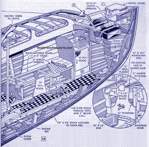
Continuing with the cabin interior, install the framing
and plywood covering of the port and starboard bunks and forward cabinets.
The top of the port-side cabinet is cut out to take a 12 x 12-in. galley
sink, which drains through the hull, as in Fig. 43. Fresh water is piped
to a faucet fitted through the bulkhead, Fig. 30. The bunk mattresses are
supported on a removable frame woven of burlap webbing as in Fig. 33. They
are kept in place by a 1 1/2-in. projection of the plywood bunk sides,
which extend down over the inboard sides of the floor stringers. The hull
ribs above the bunk frames are covered with 1/2-in. mahogany, Figs. 41
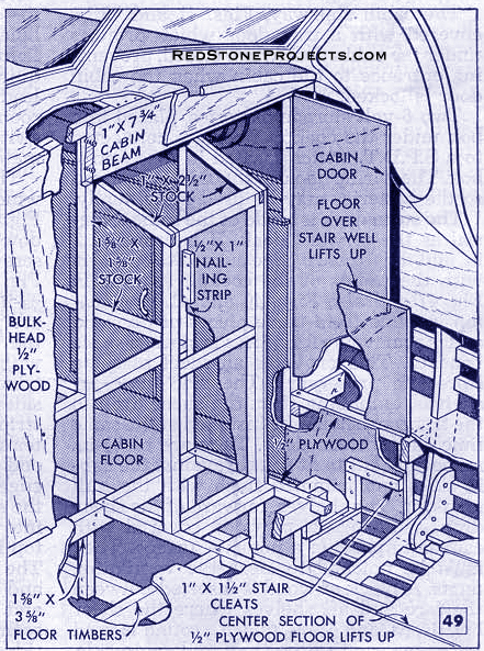
and 42. The center of the cabin floor is made in two removable sections,
each supported by cleats fastened to the |

|
Figure 44. Top of engine compartment serves as
a table when preparing food in the cruiser's cabin.
|
|
| plywood bunk sides and floor timbers which are bolted
to the frames on top of the tie bars (see station 3, Fig. 43). Note that
the floor slopes to obtain maximum headroom at station 6. The cabin floor
on both sides of the engine compartment is fastened permanently to the
top edges of the floor stringers and floor timbers, Figs. 35 and 38.
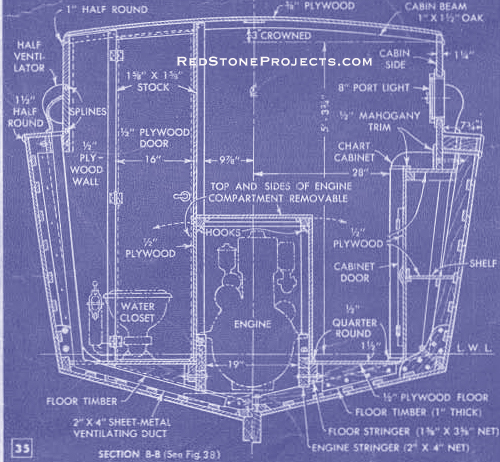
Before covering the cockpit-bulkhead framing, install
the water closet, which must be purchased from a marine supply house. Plywood
is used for the walls and doors of the toilet room, engine compartment
and chart cabinet. Note in Fig. 35 that the sides and top of the engine
compartment are removable. They also must be lined with asbestos. The sides
are held in place at the top by hooks and at the bottom with quarter round
nailed to the floor. One side and the top are shown removed in Fig. 36.
An alcohol cooking stove is bolted in a sheet-metal cabinet mounted on
the bulkhead frame. The cabinet must be removable for access to the rear
of the control box as detailed in Figs. 43 and 49. This box houses the
compass, electrical switches, engine controls and steering gear. An inspection
door in the front of the box, Fig. 37, is held in place with brass door
buttons and plates. |
|
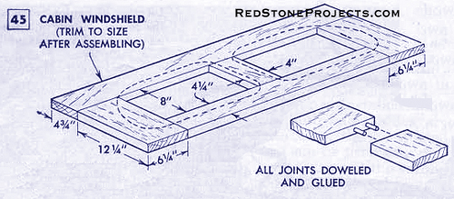
Figure 45. Cabin Windshield
|
|
| The steering system, Figs. 30 and 38, consists of an
automobile steering knuckle of the worm-gear type bolted in the control
box so that a steering wheel can be fastened to the worm shaft. The stub
shaft of the worm gear is welded to a vertical shaft extending below the
cockpit floor. Lever arms attached to the lower end of the shaft and rudder
post are connected with a steering rod of 1/2-in. pipe, which has a clevis
welded to each end. A hand-operated bilge pump is fastened to the port
side of the control box with the outlet joined to a 1/2-in. galvanized
pipe running under the cockpit floor to a hole in the transom. The pump
intake is connected to a hose extending down to the bilge.
The cabin stairway, Figs. 41 and 43, is covered with a
trap door which projects under the cabin door when closed, preventing entrance
to the cabin when the cabin door is locked.
Two 6-volt storage batteries, placed in a box under the
cockpit floor are connected to a S.P.D.T. switch located in the control
box. The wiring hookup should be arranged so the batteries may be used
individually. |
| The stern deck is made of the same material as the forward
deck. It is crowned 2-in. and the forward edge curved to conform with the
radius of the cockpit seat, as in Fig. 47 and also Figs. 40 and 41. The
seat top is made from three pieces of plywood and is removable for access
to storage space beneath. This provides an ideal place to store life preservers.
The side decks or shelves, extending from the sheer drop to the transom,
should be installed at the same time as the stern deck. They are of 3/4-in.
mahogany cut to fit snugly against the cabin sides and trimmed flush with
the hull planking. The shelves, forward of the sheer drop, are of 3/4-in.
plywood covered with canvas to provide a nonslip surface. They must be
notched to clear the ventilating ducts. A block of wood is inserted between
the fore and aft shelves where the sheer line drops, and 3/4-in. quarter
round is used along the joint of the shell and cabin side. |
|
Figure
47. Perspective of Inboard Profile
|
Get a restored copy of these vintage Sea Craft 25
Foot Cabin Cruiser Plans with 69 Pages of Enhanced and Enlarged
Figures and Illustrations and Searchable Text.
All Orders Processed
On a Secure Server
|
|
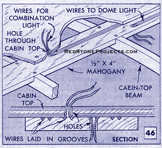
| Before the cabin top is put on, cut grooves in the center
strip for the insulated electrical wires, as in Figs. 46 and 47. These
wires, which are connected to switches on the control-box panel, are brought
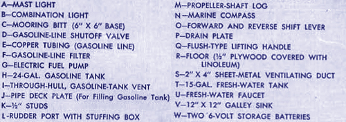
through holes in the cabin top to the combination light, mast light and
a horn which is required for a boat of this size. The wires leading to
the cabin dome lights and toilet room wall light, which have individual
switches, are connected directly to an amp meter on the panel. |
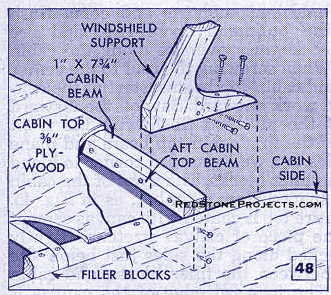
| The two outer supports for the cockpit windshield are
shown in pattern squares in Fig. 41. Each side is made from two pieces
doweled and glued together at the top and screwed to the top edge of the
cabin sides, Fig. 48. For the cabin roof, two pieces of 3/8-in. plywood
4 x 12 ft. are needed. These are joined at the center, notched to clear
the windshield supports and come flush with the bulkhead covering, and
are trimmed slightly oversize along the cabin sides. When screwing the
roof to the center strip and cabin-top beams, start at the center and work
outward. Saw off the forward end of the plywood flush with the front edge
of the first cabin-top beam and plane the sides to a well-rounded corner
to blend into the filler blocks. The front of the cabin top is shaped from
a timber, as in Fig. 45. |
| The entire top is coated with canvas cement and one piece
of canvas stretched tightly and tacked along the sides just below the seam
between the filler blocks and cabin sides. The forward edge of the canvas
is tacked under the front edge of the shaped timber and the aft edge is
tacked to the bulkhead; the canvas then is given several coats of thinned
paint. Half-round mahogany molding covers the tacked edges of the canvas
along the cabin sides and bulkhead. The cockpit windshield is completed,
as in sections F-F and E-E of Fig, 41. The mast, also detailed in Fig.
41, supports a white light. Section D-D of Fig. 41 gives the dimensions
of handrails fitted to the cabin top. |
|
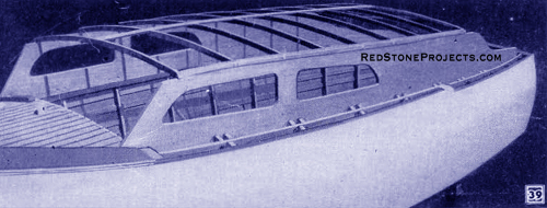
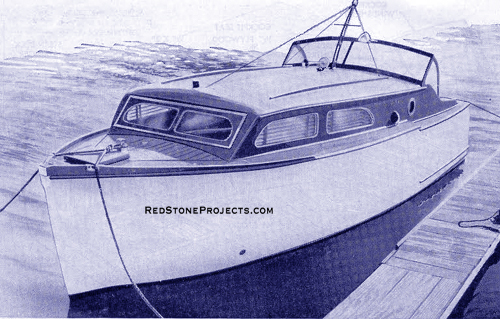
Sea Craft's lines show the best advantage when
viewed off the bow. Cabin roof can be used for sun bathing.
|
|
| The cabin windshield, Fig, 45, fits into a rabbet cut
in three pieces of 1 1/2-in. stock, two of which are screwed to the forward
edges of the cabin sides, section C-C of Fig. 41, and one placed horizontally
across the forward deck, Widths will vary somewhat with each boat. Note
in Fig. 47 that the rabbet on the athwartship piece is cut at an angle
to fit a 36-deg. bevel on the lower edge of the windshield. Toe rails extending
from the breast hook at the bow to station 4 on both sides along the sheer,
Figs, 40 and 41, are screwed to the deck planking as in the upper detail
of Fig. 42. The seam between the hull and deck planking at the sheer is
covered with 1 1/2-in. half-round molding. This also is used for the guard
rail at the aft end of the hull, Fig, 41. The hatch cover for the chain
locker should be a snug fit. It is planked with l/2 x 3-in, mahogany over
1/4-in. plywood, which is rabbeted into the top edges of the cover frame.
Before painting the exterior, mark the L.W.L. on the hull
and fill the planking seams above this line with a fresh or saltwater seam
sealer. Give the hull three or four coats of flat-white marine paint above
the L.W.L., sanding the hull by hand after each coat. Then apply a mixture
of flat and glossy white paint and follow with a coat of glossy white.
The decks, cabin sides and windshield frames are sanded, and a mahogany-colored
wood filler or a stain is applied, after which three coats |
| of marine varnish are applied, sanding the first two
coats. Deck-plank seams are filled with a white seam sealer before varnishing.
All exterior hardware is installed next. The fore and
aft mooring bitts must be bolted securely in position to withstand considerable
strain, Plate glass for the windshields and cabin windows is held in place
with lead beading, as in Figs, 31 and 41. Mahogany on the interior of Sea
Craft's cabin was stained and varnished and the plywood painted white,
as in Fig. 44. The boat must be provided with a fire extinguisher which
should be mounted on the cabin side wall above the chart cabinet. Give
the bottom of the hull another coat of copper bottom paint and launch while
the paint is wet.
A boat of this size must carry registration numbers. Application
for a certificate of award of number can be made by the boat owner to the
District Coast Guard Officer having jurisdiction over the area in which
the owner resides. |
|