Free Shipping on All U.S. Orders
All Orders Processed on a Secure Server
Build a 14 Foot Canned Ham Trailer
Complete Vintage Wanderer Travel Trailer Plans
|
Vintage Wanderer Travel Trailer Plans
Build this Post-War Canned Ham Style Cabin Trailer
 |
PDF Format |
|
|
All Orders Processed
On a Secure Server
|
Price $12.95
|
|
Get a restored copy of these vintage Wanderer Canned
Ham Trailer Plans with 50 Pages of Enhanced and Enlarged Figures
and Illustrations and Searchable Text.
|
We will email these plans, to the address provided
with your payment, within 48 hours following receipt of your order.
|
|
|More
Vintage Trailer Plans|
|
|

|
|
| Build the |
|
Cabin Trailer "Wanderer"
|
|
and go places!
|

| By JOHN GARTNER
Part 1
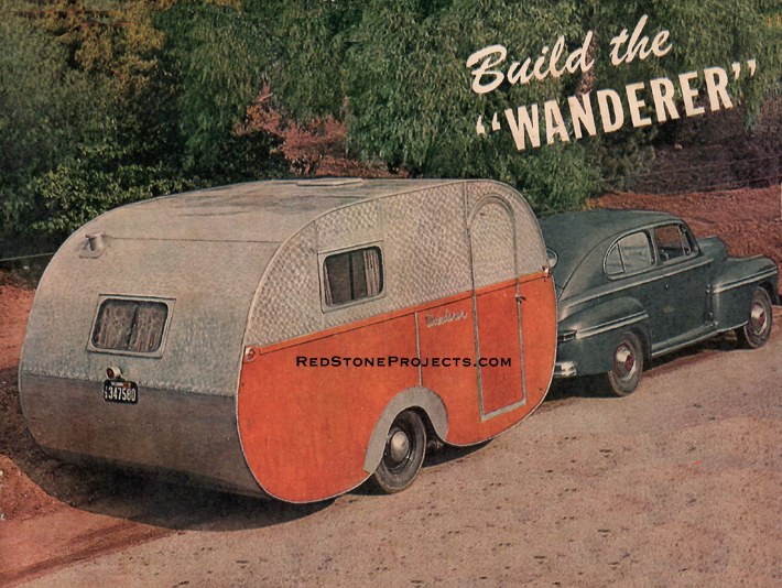
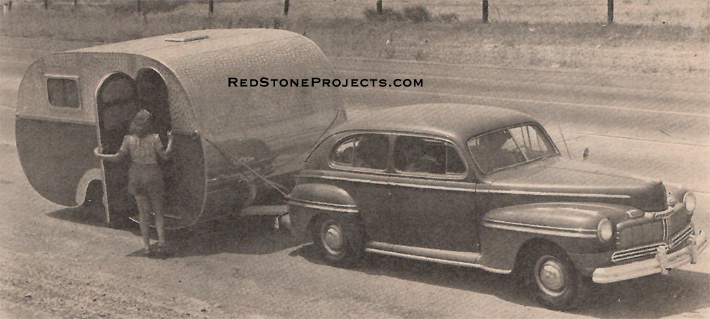
ROOMY as a 20-footer but light enough to haul anywhere,
the 14' cabin trailer WANDERER which can be built in your own back yard
with ordinary hand tools, boasts a floor plan and construction as modern
as tomorrow. It is the ninth trailer project undertaken by the builder
since 1932 and incorporates the best features of all its predecessors.
Last summer our family of five spent three months, travelled
5000 miles all over the West, and had the vacation of our lives in her.
WANDERER is a quality job throughout and duplicating the
likes of her in the open market would cost around $2000. However, she can
be built and furnished, even at today's inflated prices, for less than
half of that sum. This includes purchasing many of her construction parts
such as the complete undercarriage with brakes, refrigerator, window, stove,
sink, etc., from trailer supply houses which furnish such items. The builder
who wishes to make some of these parts himself can get by with even less
cash outlay. |
|
|
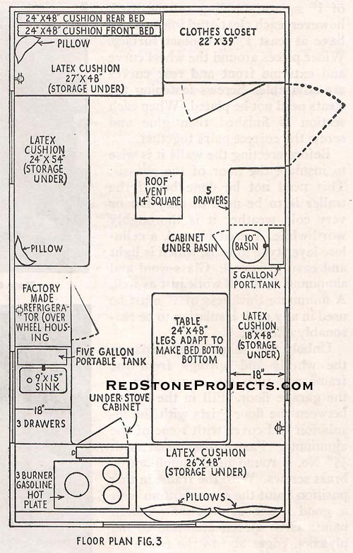
| Here are her main features. Completely furnished with
beds, stove, water tanks, etc. she has a certified weight of 1870 pounds.
She has a 14-foot body, slightly over 15' including the tongue, a 7 1/2
foot width, and 8' of overall height. She has a large clothes closet, latex
cushioned beds for four (extra space for a child's cot on the floor), loads
of drawers and storage space, three-burner gasoline stove - may be adapted
to bottle gas if preferred - large 75 pound refrigerator, sink, wash basin,
commode, sitting space with table removed for 10 or more persons, dining
space for six, has underslung springing for steadiness, electric brakes,
hardwood interior and aluminum exterior, and the most livable arrangement
in any coach of its size available today.
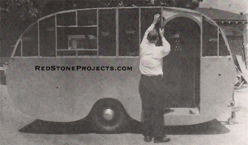
But let's get down to details. First, all drawings and
photos must be studied thoroughly before beginning construction. Many difficult
points will be clarified by the closeup pictures of the actual building
of WANDERER. There may be slight differences in minor points between the
drawings and the photos. In these cases, the drawings show refinements
which should be adopted. |
|
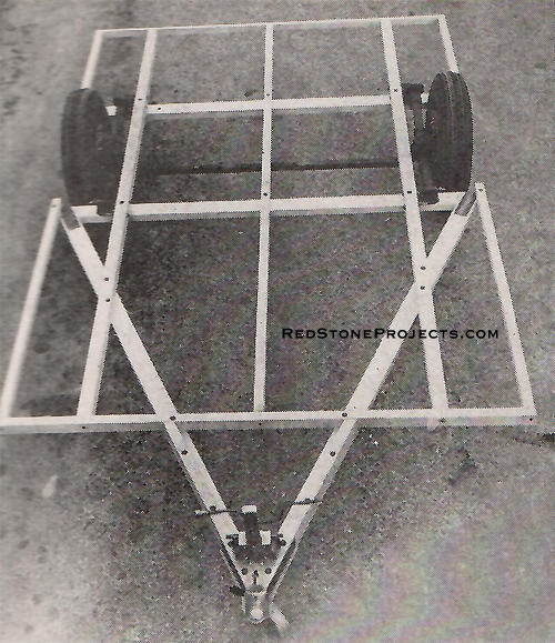
Photo 1. Chassis without aluminum bracing.
|
|
| Look over the main materials list very carefully. It
is best to procure all of these items before beginning actual building
so that any necessary adaptations in design may be made.
Windows, chassis, refrigerator, etc., may be made by the
builder but the manufactured parts are relatively inexpensive, are easy
to install, and make the finished product more like a fine factory-built
job. |
|
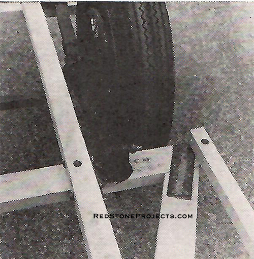
Photo 2. Typical underslung spring installation.
|
|
| The chassis should be built first and is shown in detail
in Figs. 1 and 2 and Photo 1. It is of wood, preferably spruce or hardwood,
and is reinforced with metal angles.
Many potential builders will throw up their hands in horror
at the thought of a wooden chassis and to these I suggest that they go
ahead and build it of steel. Use 4" channel iron for the crosspieces, 3
x 3 x 1/8" angle iron for the tongue, and 2 x 2 x 1/8" angle for the longitudinal
pieces. Steel construction will add about 150 pounds to the total weight
and in my opinion is unnecessary. Thousands of wooden chassis trailers
have been built commercially and have proven entirely satisfactory.
Remember the old Franklin car? Besides wood can be worked
in your own home shop while steel usually requires professional blacksmithing.
Final dimensions of the chassis framing will depend on
the undercarriage assembly you are using. The one shown on WANDERER is
a Hammerblow Torqueless 2500-pound capacity drop axle with tread extended
10 inches and shackles adapted for underslung installation and drilled
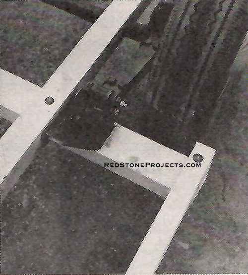
for bolting to the wood members. See Photos 2 and 3. Be sure the shackles
are fastened to both the cross and longitudinal members for extra strength.
The aluminum extrusions or steel angle irons are screwed at 12-inch intervals
with 1/4 x 1 1/2" lags to the lower edges "A," as shown in Figs. 1 and
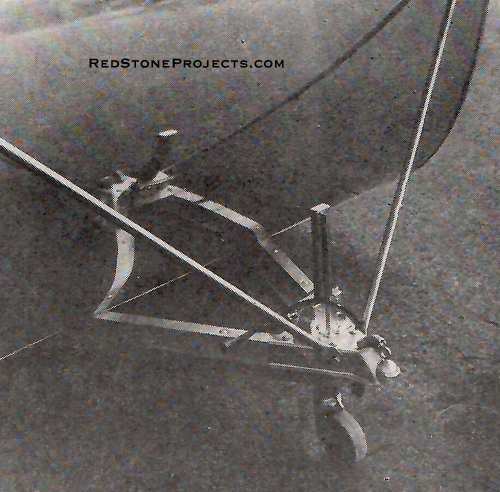
2. The hitch shown is an Atwood combination with jack. See also Photo 15.
|
Photo 3. Typical spring installation.
|
|
| No detail on brakes is given as maker's installation
instructions should be followed. Warner Electrics are used on this job
but vacuum brakes are perfectly satisfactory.
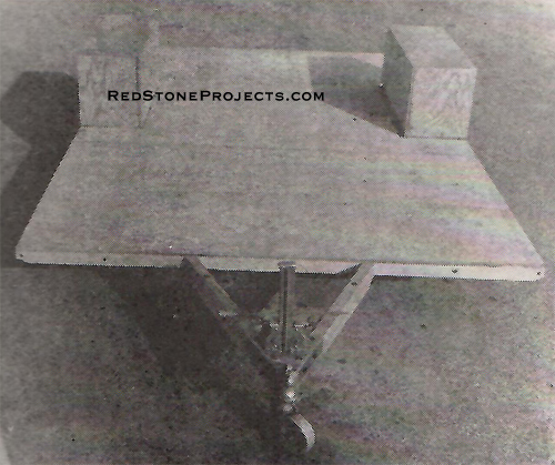
Three pieces of 1/2" waterproof five ply 4 x 8' are used
to lay the floor. Two full widths are fitted to the front and center on
the four-foot beams as shown in Fig. 1 and Photo 4 while the third piece
will have to be sawed to fit. Water-mix waterproof glue and 1 1/4" flathead
countersunk screws are used to fasten this securely and to add materially
to the strength of the chassis.
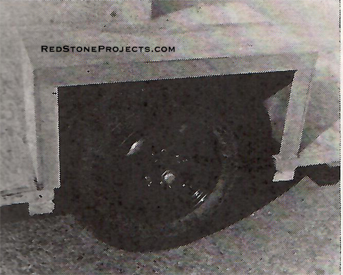
Cut out the wheel housing openings carefully and plane
side edges flat and smooth so the side walls will fit snugly. Waste ends
of these floor pieces can be used in building the wheel housings.
After the floor is on, reinforce the tongue still further
with 2 x 2" pieces edge bolted as shown on Figs. 1 and 2 and Photos 1,
4, and 15. If you use steel for the chassis this reinforcement is unnecessary.
Wheel housings come next. Exact dimensions will depend
on the undercarriage used, but a minimum of 4 inches clearance between
the top of the tire and the housing cover must be allowed to take care
of settling when the job is completed and loaded with supplies. Half inch
waterproof 5-ply is used for the side and ends while 1/4" or 3/16" material
is okay for the top.
Glue and screw with 1 1/4" No. 8, flathead galvanized
screws the large inside piece against the longitudinal housing edge and
butting against the front and rear housing openings. The height of the
housing will be approximately 16 to 18 inches above the floor. End pieces
come next, fastened similarly at the bottom and edge screwed to the first
piece. If the housing material is lighter than 1/2", corner cleats should
be fitted also. Pieces of 1 x 2" spruce are screwed to the outside edges
and parallel with the upper edge of the inside wallpiece before fastening
the top as shown in Photos 4 and 5. These aid in making the joints between
the wall and housings dust and waterproof. The top is glued and screwed
with 1" screws. |
|
|
Photo 4. Chassis with floor and wheel housings.
|
|
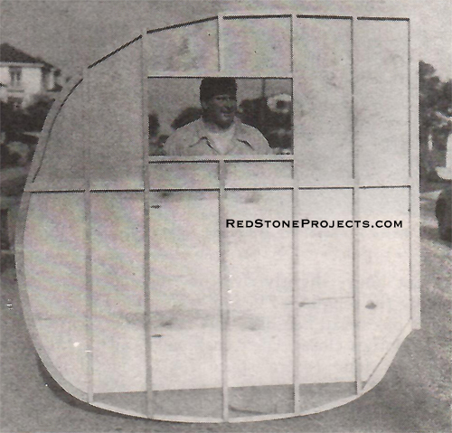
| The walls are built next. They are constructed separately
in two sections each, but are installed as a unit. See Photos 6 and 7.
Clear out a clean space on the garage floor and lay down
four pieces of 4 x 7' x 1/4" plywood to form a section 8 x 14' in size.
Make either wall first but remember that it is being built inside out and
select the best surfaces to face in. I used walnut panels for the lower
half and light gum for the upper, which gives a beautiful inside appearance
when finished. If you wish to paint the interior, fir will do as well and
cost considerably less. |
| On the plywood section mark 12" squares with chalk lines
and lay out the curves as shown in Fig. 2. A thin bending strip will aid
in fairing out the lines. |
 |
|
Figures 1 and 2. Chassis Plan and Side View with
Side Layout.
|
Get These Restored Plans
with
Enhanced
and
Enlarged High Resolution Figures
and
Illustrations
and
Searchable Text.
All Orders Processed
On a Secure Server
|
|
| Before sawing out the 7 pieces get up on a ladder a few
feet away and take a look at the general outline to see that it's smooth
and streamlined. Mark the floor line with a heavy black pencil on both
the inside and outside. File and plane the edges nice and smooth after
sawing. Clean off the chalk lines with a damp cloth after cutting. Use
one wall as a pattern for the other. Be sure and save the sawed-out door
sections for use in making the door later. |
|
Photo 6. Inside of right rear wall.
|
|
| Figs. 4 and 5 show the placing of the studs, for each
wall. Spruce 1" square is used throughout except where the plywood edges
join. Here 1 x 2" stock is necessary for extra strength. Exact measurements
between studs are important where shown. Studs are glued and screwed with
1" No. 8 nickel or chromium plated flathead screws countersunk flush. If
you have windows of a different size make the openings to fit. Leave half
of the center perpendicular joint unfastened at this time so the sections
can be more easily handled. |
|
Photo 7. Outside of left front wall.
|
|
| After the studs are placed the fill-in cleats are fitted
all around the edges. They are sawed to the exact curve on only one edge
as shown. Make the joints with the studs flush and tight so that when glued
a good bond will be affected. |
| In the flatter sections along the roof line, pieces of
1" square studding can be used, however, each cleat-stud joint should have
at least 1" of contact surface. Wider pieces around the wheel curve and
extreme front and rear curves are advisable. Screws fastening the cleats
need not be plated. When each section is finished then glue and screw the
correct pairs together. |
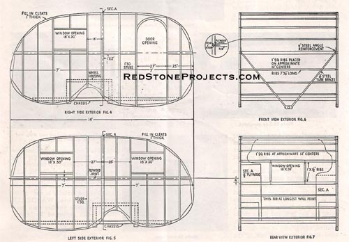
Figures 4, 5, 6 and 7. Right Side Exterior, Left
side Exterior, Front View
Exterior, Rear View Exterior.
|
Get These Restored Plans
with
Enhanced
and
Enlarged High Resolution Figures
and
Illustrations
and
Searchable Text.
All Orders Processed
On a Secure Server
|
|
| Before erecting the walls, it is wise to insulate the
floor of the chassis. This need not be done but if the trailer is to be
used in very hot or very cold weather it is thoroughly worthwhile. I used
Kimsul, a cellulose layer type in rolls, which is light and easy to install.
Glass-wool and aluminum foils will work just as well. A minimum thickness
of 1" must be used in any pack insulation to be reasonably effective. |
|
Photo 8. Outside wall ready for insulation and
aluminum covering.
|
|
| Unbolt the shackles to separate the wheels and springs
from the frame and turn the frame over on the garage floor. Fill in the
spaces between the floor joists with the insulation and cover with some
of the aluminum. Fasten the metal with 1/2" No. 8 round head aluminum or
brass screws. |
|
Photo 9. Lower panel complete and insulating lower
panel.
|
|
| With the frame in this position paint the entire bottom
with a good grade of black asphaltum paint. Give special attention to the
plywood edges and to the entire inside of the wheel housing. On wet roads
this underpart takes quite a beating and a much better protecting job can
be given with the frame in this position than waiting until later when
you have to "get out and get under!" |
|
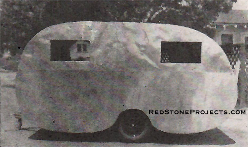
Photo 10. Side completed.
|
|
| The best job of wall installation (Photo 8) can be done
if the frame section is squared up on blocks. Replace the frame on the
wheels and roll it outside. Block up the corners so the frame is square
and level, using the car jack and scrap pieces of timber. The walls can
be put up, squared, and braced in one day and after that is done the rest
of the building can be accomplished satisfactorily without blocking and
leveling again. |
|
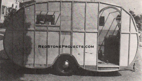
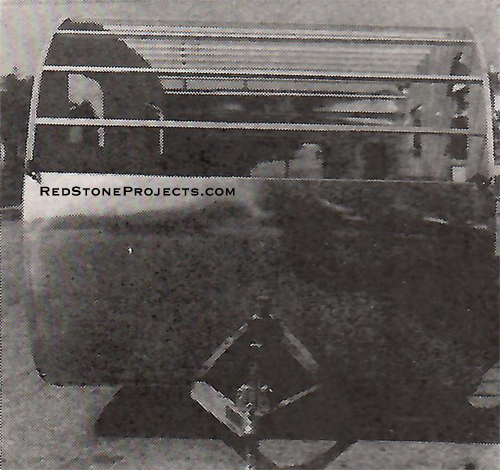
Photo 11. Front view showing roof studs and aluminum
covering.
|
|
| Up until now the chassis will roll in and out of an ordinary
garage easily. But after the walls are up, you'll need 8' of height clearance.
If the garage doors cannot be adapted, you must either rent space in a
public garage or get a big waterproof canvas tarp to cover the whole job.
A nice trailer like this should have cover during construction at least
and preferably all the time it is not actually in use. However, the completed
WANDERER will stand more weather than most trailers with siding of leatherette,
Masonite, or plywood. |
| You'll need help in erecting the walls. First check the
frame edges so that a good, smooth surface will be ready for the wall.
A good joint here adds measurably to the strength of the entire construction. |
|
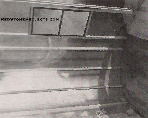
Photo 13. Inside rear interior ready for insulation
and lining.
|
|
| Before applying glue have two friends hold up a wall
section against the frame while you check the marked floor line against
the actual floor line. When this suits you, mark on the wall where the
front and rear of the frame comes. A small triangular section of the front
2 x 2" joist will show as well a part of the ends of the frame crosspieces.
There will be a space between the wall and the frame at the rear which
is to be filled in later as shown in an edge view at the rear of Fig. 2. |

|
Photo 14. A clearance light.
|
|
| Set the wall aside. Smear liberally the frame and wheel
housing edges where they will come in contact with the wall with waterproof
glue. Fit the wall back carefully to avoid soiling the inside surface with
extra glue, and nail temporarily. While your friends are still holding
the wall put three temporary braces, at each end and in the middle, from
the floor center to the wall. Fasten these braces, temporarily but securely,
so that the wall is perfectly square with the floor. Then, and not until
then, tell your friends to let go. |
|
Photo 15. Close up of hitch and diagonal braces.
|
|
| Before erecting the other side put in the permanent fastenings
because heavily mixed glue, best for this joint, sets rather quickly. Drill
each stud where it crossed the edge floor joist or wheel housing filler,
and fasten securely with 2 1/2" No. 12 flat-head galvanized screws countersunk
flush with the outside of the stud. Use 2" screws in wheel housing fillers.
Fasten also with 1" round head screws at 6" intervals through the plywood
between the studs. |
| Erect the other side and brace in the same manner. Be
sure that both sides match on the frame. |
|
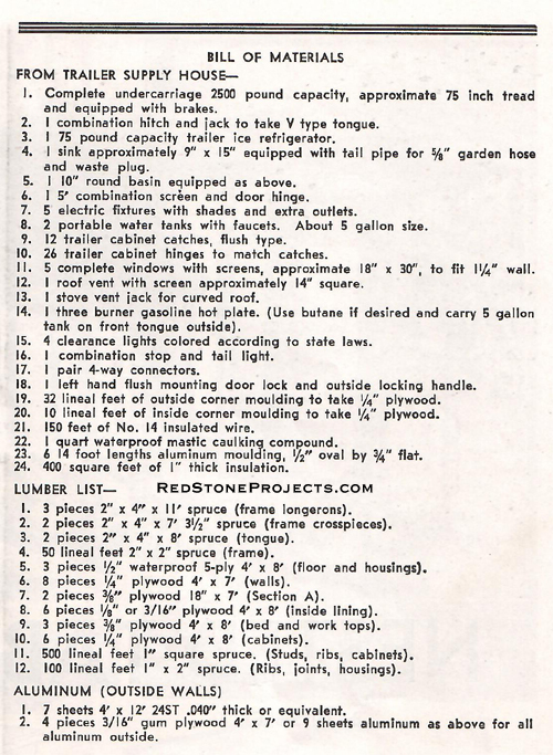
WANDERER Bill of Materials
|
|
|
| By JOHN GARTNER
IF YOU have worked weekends on your 14' cabin trailer
WANDERER you will he all ready for this second and concluding installment
on its construction (Part 1 in previous issue, Jan.-Feb. '47). About 40
full working days were involved in building the original and since the
inside cabinet work takes a greater proportion of the time we'll move right
along.
Roll out the chassis with the side walls erected and plan
the location of the ribs. See Figs. 6 and 7 and Photos 11 and 13 (Part
1). Cut a dozen pieces of 1" square and 3 pieces of 1 x 2" spruce 7' 3
1/2" long for a starter. Bevel off the lower front edge of the frame so
it is flush with the side walls. Measure from the lower edge of this bevel
around the wall 4' and mark for the placement of a 1 x 2" rib. This must
be kept in mind in all rib placements as the aluminum comes in 4' widths.
A 1" lap is to be allowed for each joint. Fit three more 1" square ribs
at approximate 12" centers in the space between.
Ribs are to be fastened by drilling the walls to take
a 3" No. 10 flathead screw into the end of each rib. See drawings 6 and
7. This construction will not seem too strong at first, but when the metal
covering is attached firmly to both the wall edges and the ribs it becomes
very rigid and strong. |
|
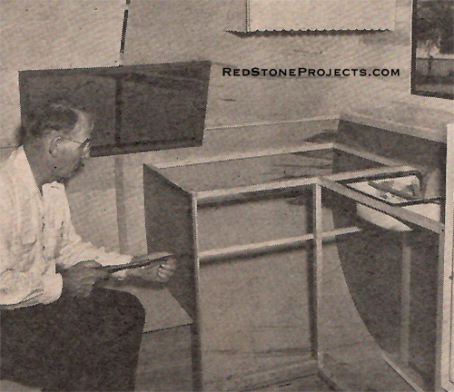
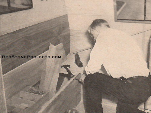
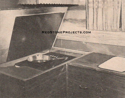
Photo 16. Building L type stove and sink arrangements.
|
|
| Measure off another 4' from the lower edge of the top
rib and repeat as before. This will allow for the second panel of metal.
The 1 x 2" rib at the point where the upper and lower sections of plywood
wall meet is to be reinforced on the upper edge with a 6" steel angle brace
screwed to the rib and to the wall. See Drawing 6. This is necessary to
have a secure base to hold the steel tube diagonal braces to be installed
later. In actual road work these braces take a lot of the stress off the
tongue and steady the whole trailer. |
|
Photo 17. Drawer chest and basin.
|
|
| Do not go any farther with the front ribs now but go
to the rear and begin again. This is done because at the top there will
be a section of roof that must overlap downhill both ways. |
|
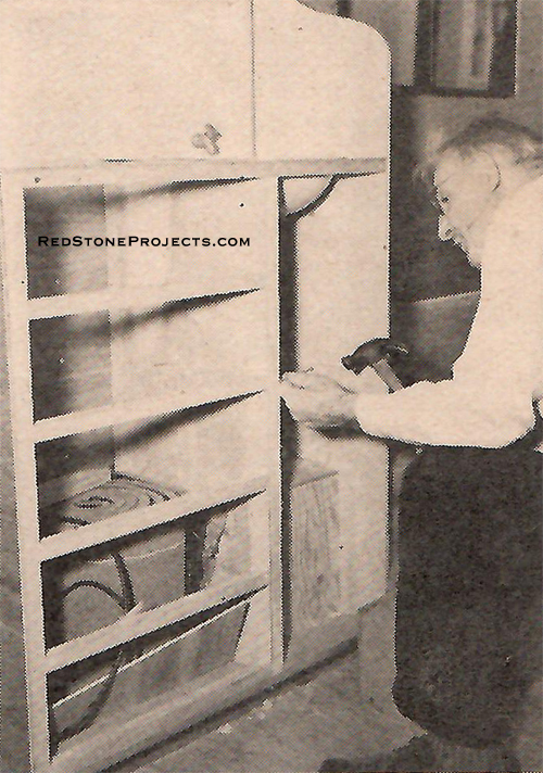
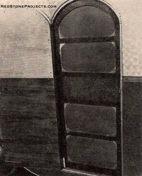
Photo 18. Fitting clothes closet door.
|
|
| Cut a piece of 3/8" waterproof plywood to fit flush with
the floor top, butt against each side wall, and flush with the lower edge
of the walls just at the rear of the chassis frame. See edge section at
rear of Fig. 2 (Part 1). Glue and screw this carefully to the frame. Cleat
the walls with a section of 1" square spruce to fasten this piece to. Run
a rib along the lower rear edge of this plywood piece and then bevel it
off flush with the walls to take the lower edge of the first metal panel
in the rear. |
|
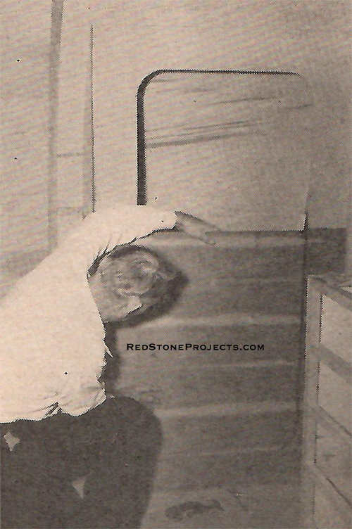
Photo 19. Fitting overhead cabinets.
|
|
| Measure up 4' and install another rib as at the front.
Then put in three more at approximate 12" intervals as shown in Fig. 7
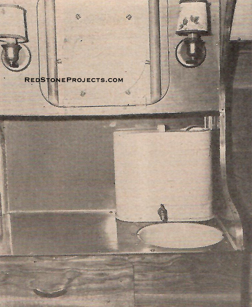
(Part 1). Set another rib 4 feet above the top one as before. In between
place the 1 x 2" ribs which mark the upper and lower edges of the rear
window. See Photo 13 and Fig. 7 (Part 1). The lower window edge is dropped
4" below the plywood joint line. Fit two 1" side pieces so that the window
is centered. A regular rib is then placed in the upper space but spaced
so as not to interfere with the placing of the stove vent. See Fig. 8. |
|
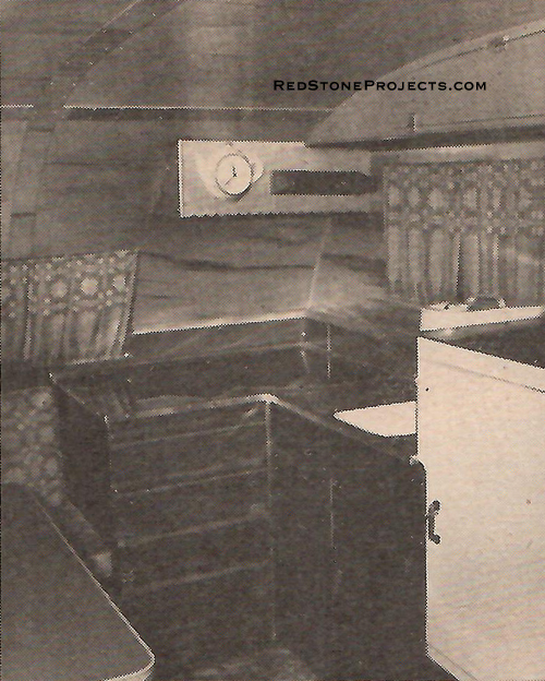
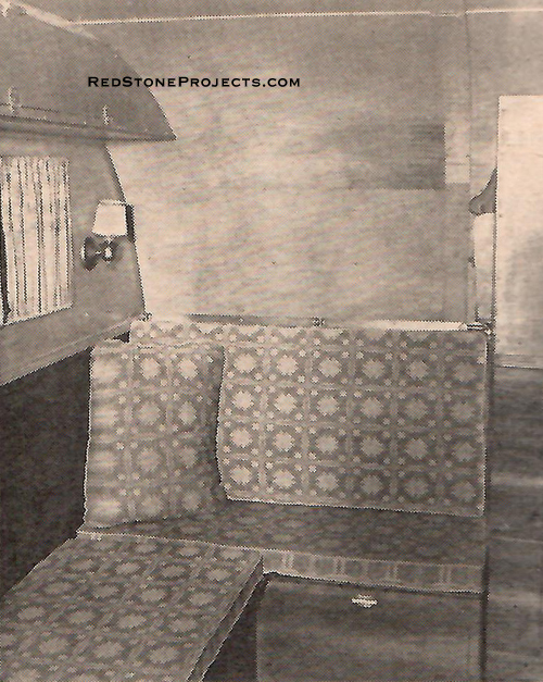
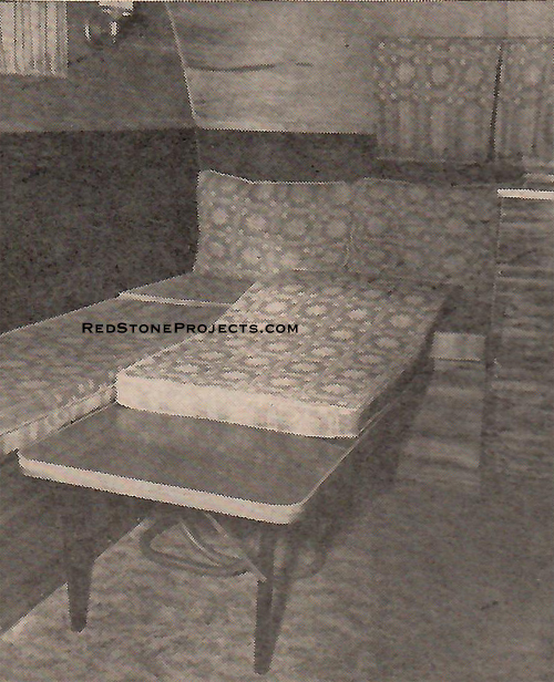
Photo 20. Dinette seats at right rear.
|
|
| Work out another 4' section as before along the middle
portion of the top. About 12" ahead of the center plywood joint section
allow a 14" space between two rib edges at approximately the highest point
of the roof to take the roof vent. Fit two cross-pieces to these ribs so
that the vent will be centered similar to the rear window. |
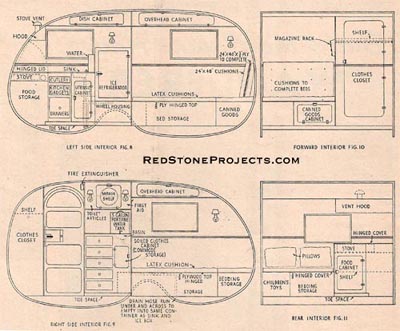
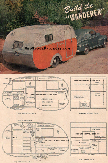
Figures 8,9,10 and 11. Left Side Interior, Right
Side Interior,
Forward Interior and Rear Interior.
|
Get These Restored Plans
with
Enhanced
and
Enlarged High Resolution Figures
and
Illustrations
and
Searchable Text.
All Orders Processed
On a Secure Server
|
|
| Checking now you will find there remains about a two-foot
section as yet unribbed. Fit another rib in here equidistant between the
others. The temporary wall braces should remain in during this construction
and also during the placing of the aluminum roof. |
|
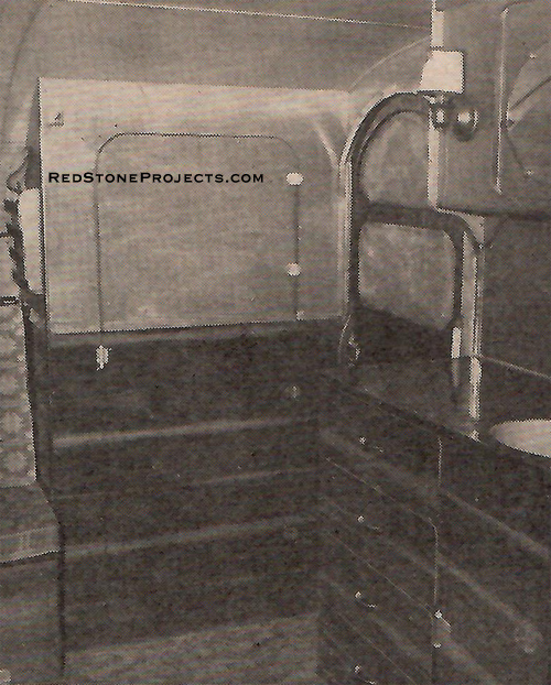
Photo 21. Right rear interior with finished kitchen.
|
|
| The aluminum roof and ends comes next. The metal should
be what is technically known as 24ST in a thickness of .040 inch. This
is tempered and has more stiffness than the SO type. Heavier material can
be used although it is not necessary. I got my aluminum from an aircraft
salvage yard but it can be purchased in standard 4 x 12' sheets from the
larger sheet metal companies. Corner construction will be difficult, however,
with the corrugated material.
An electric drill is almost a necessity in preparing the
metal. The best fastening is a duralumin or aluminum wood screw in a 3/4"
No. 12 round head size. When placing the screws, holes should be drilled
a trifle larger than the screw to allow for expansion and contraction of
the aluminum which is notoriously susceptible to extremes of heat and cold.
WANDERER has withstood everything except actual freezing weather. |
|
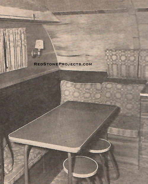
Photo 22. Left rear interior finished with dinette.
|
|
| If you can't obtain aluminum screws use brass or bronze
as second choice and galvanized as a third selection. (Pacific Metals,
1100 S. Alameda St., Los Angeles, California, stocks aluminum screws and
nails.) Brass makes an appealing combination with the silver aluminum but
both it and steel will produce a minor degree of electrolysis with aluminum.
And even the best galvanizing will rust, especially in the salt air of
the beach areas.
With a heavy tin shears cut five 7' 5 1/2" lengths of
4' wide aluminum. Take care with this as the metal scratches easily. Drill
screw holes at 3" centers along the lower long edge of one piece, so that
they will center in the beveled area you make on the lower front edge of
the frame joist. Smear some waterproof mastic caulking compound along the
beveled edge and screw the metal panel to it after first squaring on the
trailer body so that there is a 1/4" margin between the metal and the outside
wall edge. See Photo 11 (Part 1). |
|
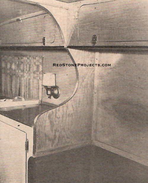
Photo 23. Front right interior finished with closet
and chest drawers.
|
|
| Hand bend the aluminum around the curve and clamp to
the 1 x 2" rib with thumb clamps. Place a straight edge on the aluminum
outside the ribs and scribe a pencil line centering each rib to mark the
screw holes. Drill as before and place each individual screw in waterproof
mastic before inserting. This never hardens and makes the screw holes waterproof.
At the top fit another piece of aluminum lapped over the
first one and fasten as before. Where the metal contacts the wall edges
drill or punch small holes approximately 2" apart to take aluminum or brass
flathead nails not more than 1/2" from the edge. A 3/4" moulding set in
mastic will cover this as a finishing strip later. |
|
Photo 24. Left front interior finished with sitting
room couch.
|
|
| Now go to the rear and follow the same process with the
remaining three pieces of aluminum. Cut out the window and vent sections
with a hacksaw after the metal panels are fitted. Fasten the aluminum around
the window and vent edges with small nails as you did the wall edges.
Now cut a 7' 5 1/2" piece of aluminum just wide enough
to fill in the uncovered space allowing for a 1" lap at each end. The upper
edge should be lapped under the top metal and over the lower. With each
joint and screw hole masticed the roof will be permanently watertight.
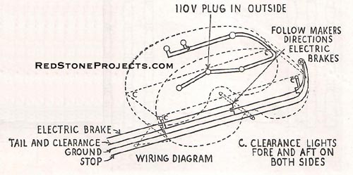
Wiring comes next as shown in the wiring diagram. A straight
job of parallel wiring with No. 14 insulated wire takes care of the 110-volt
circuit and its five combination lights and outlets. The plug in is carried
high on the left side so that it is out of the way of persons walking around
the trailer. Just drill the studs close to the inside walls and run the
wires through. |
| Tail, clearance, and stop light installations are also
shown, Run the wires under the trailer and drill through the apron at the
frame rear to get inside the body. For the front clearance lights go up
through the front frame joist just behind the aluminum sheeting. When no
110-volt current is available a battery electric or gasoline lantern is
the most practical lighting.
Next comes the insulation. If Kimsul is used it can be
cut just a trifle wider than the openings and it will stay in place while
the siding and lining is being put on. Glass wool will have to be glued
in place. See Photo 9 (Part 1) It is advisable to fasten any sidewall insulation
at the top to keep it from settling down in the wall when the trailer is
being towed on rough roads. |
|
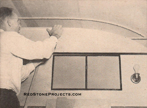
Photo 26. Section A closeup.
|
|
| WANDERER has a 3/16" gum plywood panel on the lower outside
section of each side purely for appearances. See Photos 9, 10 (Part 1),
and the completed job. A better weather resisting construction is to cover
the whole side with aluminum. A lap joint would suffice for the 2" arrow
moulding shown in Photo 14 (Part 1) and save a lot of work. But the wood
paneling makes a striking job when it comes to looks. The sections of aluminum
left from the roof pieces can be used on the upper sides. Make butt joints
at any stud and cover with a 3/4" half round aluminum moulding.
In fastening the metal edges on the sides keep the nails
as close to the edge as possible as the moulding on the side is only 1/2"
deep. |
|
Photo 27. Kitchen closeup.
|
|
| Six pieces of 4 x 8' gum panel either 1/8" or 3/16" thick
is used for the inside lining of the roof and ends. Insulation must be
placed first, however. For ease of installation the lining is fitted with
an open center joint which will later be covered with a 3" strip of the
same material. See Photos 16 and several of the finished interior shots.
Trim each panel first to an approximate 43" width. Start
at the rear and make a good joint at the walls. If the end does not center
on a rib, don't worry, we'll fix that later. You may have to dampen the
lower of end of these panels in order to get them to take the relatively
sharp bend. Another help is to get plywood with the facing grains running
across. Screw to the ribs with nickel or chrome-plated flat head 3/4" screws
pulled up flush.
Now go to the front and fit another pair of panels with
the lower edge on the second rib up. Later a small section of plywood is
fitted to cover this space. This spacing is necessary because three 8'
pieces are not quite long enough for the whole interior.
When these pieces are fastened take the last pair and
fit to the top ribs. You may have to glue the insulation here to keep it
from failing down while you work. To make a finished job on the ends drill
through the overlapping sections and fasten with 1/2" big threaded metal
screws which will pull the plywood together without a backing rib. See
Photo 23. |
|
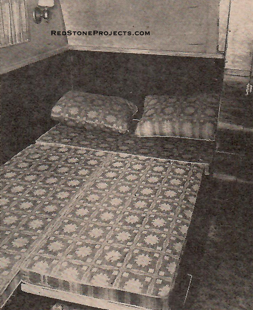
Photo 28. Front bed made.
|
|
| Now that the complete shell is finished you will find
that it is quite rigid except for the center roof area. Most conventional
trailers have closet built-ins here which give it stiffness as well as
clutter wp the interior and make it seem small. But our layout is roomy
and different and, for that reason, extra bracing must be installed in
this area.
Check the sections of circle "A" on Fig. 7 (Part 1) with
exact locations shown on Figs. 4 and 5 (Part 1). These reinforcements are
made of two pieces of 3/8" plywood each 18" wide and about 6' 5" long.
They are shaped as shown in the section drawing. A careful study of Photos
17 and 26 will give the details of the construction.
Before fitting these pieces set a temporary brace from
the floor to the ceiling at the center so that the roof is given an inch
or so rise. Cut the "A" sections with a slight taper at the top. This aids
in draining water from the relatively flat section of the roof at this
point. A pair of crosspieces on edge, made of 5/8 x 1 1/2" fluted moulding,
are screwed through on both sides of the "A" sections. Fill in the open
portion through the center with a strip of 3/8" plywood 1 1/2" wide so
the cross beam will be solid. Moulding cleats along each wall over the
plywood joints, and 1" square pieces around the wheel housings make bases
on which to glue and screw the section "A" panel. |
|
Photo 29. Dinette bed made.
|
|
| Windows and roof vents come next. They should be purchased
to fit a 1 1/4" wall and complete with screens. Be sure and use waterproof
mastic when setting these parts.
The door is built up in the same manner as the wall. A
study of Photos 31 and 32 and Fig. 9 will help in understanding how the
door is made. Spruce pieces 1" square are run around the door opening on
the inside and to these are lipped some 1/4" plywood about 1/2" for the
door to close against. Additional dust and weather tightness of the door
is given with an extra 1/2" aluminum lap over on the outside. Photos 23,
32 and outside shots will help show this.
A special continuous door hinge is used with combination
screen door flaps. Make the screen door of a piece of 3/4" or 1/2" plywood
cut out as shown in Photo 32 and Fig. 9. Screen the cutout openings and
back up the upper and lower halves with plywood so the entire thickness
is about 3/4". Make a sliding piece of material the same thickness as the
basic screen door and hold it in place with lipped pieces as shown in Photo
31. This allows the lock to be operated when the screen is not in use and
in turn fills up the open space when the screen is in use. The screen door
handle is sawed from a 1" maple block to fit. Two 2 1/4" machine bolts
3/16" in diameter are set in the door above and below the handle. They
extend through holes drilled in the screen door which is held to the actual
door with thumb nuts when not in use. |
|
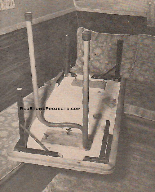
Photo 30. Table leg closeup.
|
|
| Details are shown for all interior built-ins in Figs.
8, 9, 10, and 11 and Photos 16 through 32. Most individual builders like
to adapt these somewhat to fit their own desires so no printed instructions
will be given. A few general hints, however, will be of help.
All framing is of 1" square stock and it takes quite a
bit of it. Cabinet facings are of 1/4" plywood except the bed and work
tops which are 3/8". Inside and outside corners are a special metal moulding
obtainable at trailer supply stores or you can make your own joints. Other
metal finish mouldings shown in the photos can be found in the linoleum
departments of large department stores. The imitation tile used around
the basin and sink can also be purchased in these stores. Latex cushions
must be made to order by a mattress company. They are very expensive, but
are quite comfortable over a board base.
The beds are made by filling in a 24 x 48" cushion in
both the living room and dinette L's. The table legs are removed, see Photo
30, and shortened sections of old card table legs fitted as shown to bring
the actual table down to the correct level at night. Instead of bending
tubular steel legs straight pieces can be threaded to screw into flanges
fastened to the underside of the table. In the front a reinforced section
of 24 x 48" plywood 3/8" thick is barrel bolted to the permanent seats
with the outside corner supported by a folding leg or a stool placed under
it. During the day it is stored as shown in Fig. 8. Photos 22, 24, 28,
and 29 show the bed procedures. |
|
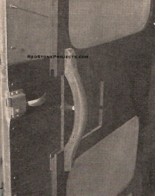
| In finishing the exterior, run angle aluminum moulding,
1/2" oval side and 3/4" flat top, set in mastic entirely around each wall.
Crawl under and asphaltum paint the exposed plywood edges and skirts. Bolt
the 3/4" steel tubing to the hitch and through the outside ends of the
wide rib with 3/8" steel bolts as shown in Photo 15 and Figs. 2 and 6 (Part
1). First flatten one end and fit to the hitch so the correct angle and
length can be figured for the upper hole spacing.
Although aluminum will not rust in its natural state it
is far better to wax the entire job regularly. If you use plywood on the
lower panel, give it a coat of thinly mixed waterproof glue before applying
two or three coats of good outside varnish. Wherever a joint is exposed
to the weather it should be waterproofed with auto top sealer obtainable
at any auto supply store.
After the clearance and tail lighting is installed, the
trailer is ready for its shakedown cruise. Have a good blacksmith install
the hitch ball on the car and if you are not an electrician have the necessary
wiring done on the car. There will be about 200 pounds of tongue weight
which will not require overload springs unless you carry several passengers
in the rear seat and heavy luggage in the trunk. |
|
Photo 32. Screen door closeup.
|
|
| If you plan on using WANDERER in very cold weather a
heater of some type must be installed. Gasoline, bottle gas, kerosene,
oil, and electric types are available. In ordinary summer touring night
chill can be taken off by burning a two mantled gasoline lantern.
The burnished circles as shown on WANDERER were made with
a small brass wire brush drilled and fitted to an electric drill chuck.
If this is done the surface must be waxed as the burnished circles oxidize
rather quickly. I had to do this as some of my aluminum was pretty well
scratched when I got it and without burnishing would have detracted from
the general appearance. That about covers it and if you enjoy WANDERER
as much as I do, I'll feel amply repaid for designing her. |
Any 2 Vintage Trailer Plans
$19.95 FREE Shipping |
|
Select 2 Vintage Travel Trailer Plans
|
|
|